Category Archives: Raspberry Pi

Mac OS on 68k QEMU

Mac OS on 68k QEMU

UPDATE 31st July 2024 – This post has been updated to reflect more recent versions of QEMU m68k as I was notified that the instructions I had followed were out of date. The 68k specific patches have more recently been integrated into the main build and so it is no longer necessary to use the q800.upstream branch I originally used.

UPDATE 1st November 2024 – Last night I was able to build and run 68k QEMU on an 64bit ARM based PineBook Pro running Manjaro Linux. Manjaro uses yum instead of apt, so grabbing software was different, but all I needed to do was update installed software, then I installed the repository’s copy of qemu-system-m68k (a lazy way of getting most dependencies), then I had to install the build environment ninja. After that, everything worked exactly as described below, although compiling took quite a while. I haven’t benchmarked the system, but it feels like it runs pretty well. Mac OS 8 didn’t take too long to install. Given this, I would expect this software to be happy compiling on other ARM based Linux PCs and SBCs, such as the Raspberry Pi.
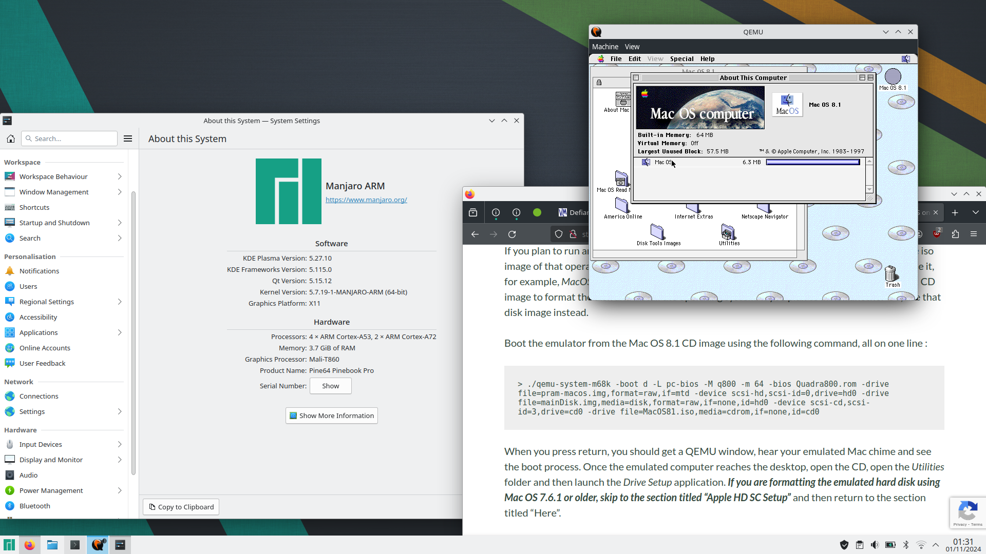
QEMU m68k Running Mac OS 8.1 on Manjaro-ARM (image)
QEMU m68k Running Mac OS 8.1 on Manjaro-ARM (click to view)

Introduction

I recently installed the 68k version of QEMU on Linux (Pop! OS) and struggled to find detailed step-by-step instructions by googling, so thought I’d upload some notes to help others. I suspect that part of what tripped me up is that previously, it was necessary to build from a branch and not the central source, which led me down the wrong path to to get the m68k variant of QEMU to build, but in truth building the main branch source now gets you to a working emulator (although not the copy in the Debian software repository). This is slightly muddied by the out of date threads that are returned as the primary results when you search for instructions on building QEMU for 68k on Linux.

Building m68k QEMU

My primary source for building qemu-system-m68k for Linux was here but ultimately I needed some guidance from a contributor to the project who saw my post and got in touch to point me in the right direction. I’m very appreciative of the time they took to help me on my way. This assumes you plan to run Classic Mac OS (between 7.1 and 8.1), and not AUX or anything more exotic.

Navigate to your home folder

> sudo apt update
> sudo apt-get build-dep qemu-system-misc ninja
> git clone https://gitlab.com/qemu-project/qemu.git
> cd qemu
> ./configure --target-list=m68k-softmmu --enable-gtk --enable-sdl --enable-slirp
> make -j4

I then copied the executables qemu-system-m68k and qemu-img from the build folder, into the folder I wanted to run them from.

Creating / Getting the Required Files

To run, you will need to generate two disk images, and a copy of the Quadra 800 ROM. Place the ROM in the same folder as the executables, and name it Quadra800.rom. I next used some of the instructions from here to work out how to generate the needed image files as follows. Run these two commands in the location you placed qemu-system-m68k and qemu-img previously.

> qemu-img create -f raw -o size=1G mainDisk.img 
> qemu-img create -f raw pram-macos.img 256b

On the first line, change “1G” to other values to change the image size from this example of 1 gigabyte.

Launching the Emulator for the First Time

The emulator “captures” the mouse (and keyboard) once you click in the window. To free the mouse, press Ctrl+Alt+g.

To initially format the disk image, you can use Drive Setup (Mac OS 8.x) or Apple HD SC Setup (7.6.1 and older) while booted from the OS installer CD. It is critical that the CD iso image you use has been properly created and includes the driver partitions and is bootable, otherwise you will just get a flashing question mark on a floppy disk icon. If you do not already have an image, you can grab one from the Macintosh Garden here (which is a direct link to download #6 (at time of writing) on this page), or from my own site here.

Rename the iso image as MacOS81.iso and place it in the same folder as qemu-system-m68k and qemu-img.

If you plan to run another version of Mac OS on the emulated computer, download a bootable iso image of that operating system, for example Mac OS 7.6.1, place it in the same folder and name it, for example, MacOS761.iso. In the following instructions I will assume that you are using a, 8.1 CD image to format the disk and install the operating system. If you plan to install another OS, use that disk image instead.

Boot the emulator from the Mac OS 8.1 CD image using the following command, all on one line :

> ./qemu-system-m68k -boot d -L pc-bios -M q800 -m 64 -bios Quadra800.rom -drive file=pram-macos.img,format=raw,if=mtd -device scsi-hd,scsi-id=0,drive=hd0 -drive file=mainDisk.img,media=disk,format=raw,if=none,id=hd0 -device scsi-cd,scsi-id=3,drive=cd0 -drive file=MacOS81.iso,media=cdrom,if=none,id=cd0

When you press return, you should get a QEMU window, hear your emulated Mac chime and see the boot process. Once the emulated computer reaches the desktop, open the CD, open the Utilities folder and then launch the Drive Setup application. If you are formatting the emulated hard disk using Mac OS 7.6.1 or older, skip to the section titled “Apple HD SC Setup” and then return to the section titled “Here”.
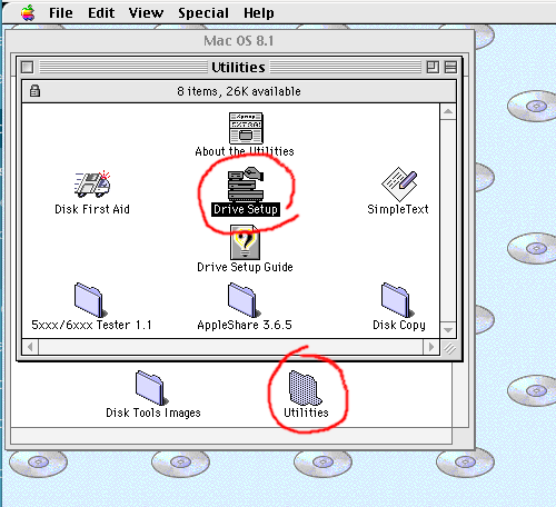
In Drive Setup, select the unformatted hard disk from the list, click the Initialize button, and then in the Initialize dialog box, click the Custom Setup… button, select “1 Partition” from the Partitioning Scheme popup menu, ensure the other popup menu says “Mac OS Standard” and not “Mac OS Extended” (if you plan to use the hard disk image with Mac OS 7.x), click OK, and lastly click Initialize. Once this is done, you can quit out of Drive Setup, and rename the hard disk you just formatted if you haven’t already. “Macintosh HD” is traditional. Once you’re done, you can install your operating system.

Here

To install an OS, navigate to the desktop. If you have just booted you will be there by default, otherwise if you are following these instructions and have just formatted your “hard disk” you may need to quit out of the formatting utility and close some Finder windows. Once you get to the desktop, open the CD and run the main installer application. Follow on-screen instructions to complete the install. If you’re unfamiliar with the process, the default settings should be just fine. Selecting Restart (if offered in a dialog box, or from the Special menu at the desktop) should bring you back up in your installed copy of Mac OS.

You can shutdown the emulated computer by selecting Shutdown from the Special menu while at the desktop.
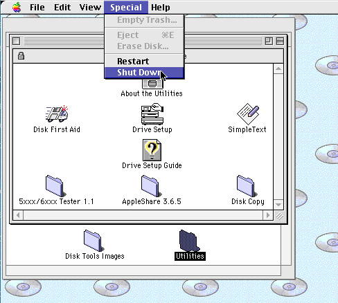
If you wish to start QEMU again, but from a different CD image, for example a Mac OS 7.6.1 iso image we downloaded and called MacOS761.iso, enter and execute the following command, which is identical to the previous command, except the CD Image filename has been updated.

> ./qemu-system-m68k -boot d -L pc-bios -M q800 -m 64 -bios Quadra800.rom -drive file=pram-macos.img,format=raw,if=mtd -device scsi-hd,scsi-id=0,drive=hd0 -drive file=mainDisk.img,media=disk,format=raw,if=none,id=hd0 -device scsi-cd,scsi-id=3,drive=cd0 -drive file=MacOS761.iso,media=cdrom,if=none,id=cd0

Once you’re done, Shutdown and we’ll set up a simpler (less typing intensive) way of launching the emulator, as well as consider a couple of helpful customisations.

Create and edit a new bash script in the folder with qemu-syetem-m68k…

> touch launch68k.sh
> chmod +x launch68k.sh
> nano launch68k.sh

Paste (right-click, paste) in the following into the file you should have open for editing :

./qemu-system-m68k -boot d -L pc-bios -M q800 -m 64 -g 1152x870x8 \
    -bios Quadra800.rom \
    -drive file=pram-macos.img,format=raw,if=mtd \
    -device scsi-hd,scsi-id=0,drive=hd0 \
    -drive file=sharedharddisk.img,media=disk,format=raw,if=none,id=hd2 \
    -device scsi-cd,scsi-id=3,drive=cd0 \
    -drive file=/dev/cdrom,media=cdrom,if=none,id=cd0

On the first line “-g 1152x870x8″ sets the display to 1152 by 870 pixels (Apple’s 21” monitor resolution) at 256 colours (8bit). If you want to run the display at 640 by 480, or 800 by 600 at 24bit colour, delete the “-g 1152x870x8” text (move the cursor with the cursor keys in nano. The default display mode allows you to switch between 640×480 and 800×600 from the Monitors control panel within the emulated computer.

If your host computer has an optical drive, the last two lines set up the emulator to directly access disks put in that drive. If you do not have an optical drive, you may need to delete these last two lines.

Press Ctrl-x and when prompted, press “y” to exit and save changes.

Now, when you want to launch the emulator, you can run the bash script launch68k.sh, for example by navigating in the terminal to the folder, and then typing ./launch68k.sh.

Apple HD SC Setup

If you format the emulated hard disk using a Mac OS 7.6.1 or older version of System 7, you will need to use the formatting utility Apple HD SC Setup. This is because older versions of Drive Setup were exclusively for PowerPCs and / or formatting IDE hard disks (and we’re emulating a SCSI disk). While the process is pretty simple, an quirk I noticed while setting up my emulator was that Apple HD SC Setup only created a very small data partition on the emulated hard disk. This is simple to fix though.

Step 1

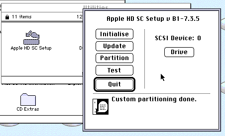
Launch Apple HD SC Setup, likely in the Utilities folder on the top level of the CD you have booted from. Select the SCSI ID of the emulated hard disk you want to format by clicking the Drive button, you most likely want “SCSI Device: 0”. Do not get this wrong or you could erase the data on whatever hard disk image you have mounted in your emulator.
Step 2

Click the Initialize button and wait. This takes quite a while.

Step 3

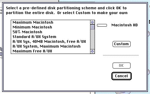
Click the Partition button, then click on the Customize button if available.
Step 4

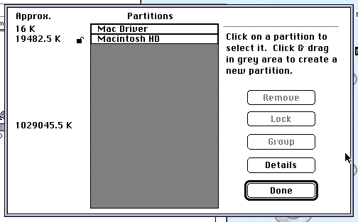
If the disk utilisation graphic shows partitions taking up most of the disk, you’re good to quit out of the utility, but if like me, the data partition is only using a small portion of the disk and the remainder is grey half tone, select the partition and click remove.
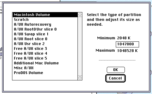
Click towards the bottom of the grey area. In the dialog box that appears, select the option “Mac Volume” on the left, and then in the text field on the right hand side, enter a value (in K) that is about 1000 less than the maximum value quoted below the text field. Click OK once you’re happy. You should now have a small amount of grey between the disk driver and the data partition. Click Done.
Step 5

Quit Apple HD SC Setup and return to the heading “Hear” above, to install the operating system.

Getting Software onto the Emulator

At this point, if you have an optical drive, you should be able to install any software you own on original CDs. This only gets you so far though. I’ve actually been moving files onto the disk image using another emulator. Basilisk II allows access to the host file system and while QEMU isn’t compatible with my Basilisk II disk images, the QEMU image works fine in Basilisk II. Other emulators might also work in this fashion, such as the Infinite Mac website, SheepShaver and others.

Make sure you don’t accidentally launch both emulators at the same time or you will possibly cause issues and corruption.

Limiting Processor Usage

On my fairly elderly laptop, when I run QEMU it consumes 100% of two cores (from the OSes perspective, as hyperthreading is on this isn’t strictly correct). This is enough to either cause the fan to ramp up to an annoying level, or if I am running from the battery, significantly reduce battery life.

The truth is, I don’t actually offer all of the speed this offers me, so I decided to look into how I might best throttle the performance of m68k QEMU to reduce the CPU time it consumes at the cost of emulator performance. Ultimately, I settled on using the program cputool which I had to install, but was available from the Debian repositories so a simple apt get install cputool sorted that.

This solution isn’t perfect as it makes the emulated graphics redraw stuttery, but it is OK if you’re mainly typing and not playing games or drawing.

After installing cputool, I was able to make a new script to launch QEMU, that just called my existing script. What I ended up with was a bash script containing…

cputool -c 50 -- ./startqemu.sh

Where “startqemu.sh” was my existing start script, “50” is the percent of each core’s total time I’m allowing. QEMU m68k uses two threads, so with this setup, I see the total CPU usage by the emulator halved and visible as 50% usage on two cores.

The above method should probably work with other emulators that consume all of an available core or core’s resources regardless of whether it is needed or not.

Advantages and Disadvantages

I’m pretty pleased with this emulator, with the only slight disadvantages I’ve seen so far (since installing an up to date version) are that it runs slower than some other emulators, it is harder to install and transferring files between the host and emulator isn’t as trivial as in emulators that mount the host file system on the desktop by default. This plays off against much better stability and compatibility when compared to Basilisk II for example, which I have been mainly using lately. One big compatibility improvement is sound. For example, SoundEdit 16 was not usable on Basilisk II due to constant crashes.

The driving factor for me trying QEMU was a bug that manifests in Basilisk II when writing software in REALbasic – if I convert an integer into a string in my REALbasic program, I get an incorrect result. This does not happen on real hardware such as my Centris 650 or my PowerBook G3, and also does not happen in QEMU.

Further Work

At this point, I should probably look into better ways of transferring files into the emulator. I believe that network filesharing, either using netatalk or possibly FTP, would be a fairly simple thing to setup. I’ve not looked into mounting the host system within the emulated Mac, I’m told this is possible, and will add instructions here when I look into it.

Obsolete Comments

This post was originally made with respect to an older, unofficial, build of QEMU with which I had a number of issues. I’ve moved the old list of issues here so that if someone is searching for terms they contain, they will still find this guide.

Issues (some minor) I experienced with the development branch and thread detailing how to build on Linux…

  • Build instructions don’t mention all dependencies.
  • Could not run configure due to permission issues if you try in a location outside your home folder, specifically on a secondary partition in my instance (I haven’t tried this again with the latest source).
  • The emulator is debouncing double clicks on my computer so they only count as a single click. It is not possible to double click in the normal manner. -fixed-
  • Disk image compatibility is very picky and the emulator does not seem to work with existing disk images.
  • After generating a disk image using QEMU’s own tool, it will not format, or even show on the emulated SCSI bus in Mac OS until you format it in Mac OS 8.1. -fixed-
  • The man pages are exclusively about x86 PCs even when called in relation to the m68k executable.
  • Resolution support is limited, more limited than real hardware.
  • The SDL mode does not work on my computer and just results in a blank screen.
  • Installing from the Debian repositories results in a non-working executable.

The most frustrating of these issues have been entirely fixed in the newer version of qemu-system-m68k, although some of the minor issues are still present (and others I haven’t re-checked for at this point). I have marked items I’ve tested and found solved as “-fixed-“.

Getting Started With Phil’s Sonoff Firmware

Getting Started

When you power on your smart relay (which is loaded with my Firmware) for the first time, an LED will light immediately – when you see this, press the button “L1”, or the only button if there is just one button and hold it for 5 seconds (or a bit longer to be on the safe side).

If you get a laptop with Wifi and look for available networks, you should see a new network starting with “Sonoff”. Connect to this – the default password is “password”.

Write down the name of this network as we will need it later.

Once connected, open a web browser and go to the following URL :

http://192.168.4.1/set?data=1111

This should turn on the relays (and indication LEDs). Now go to the following URL :

http://192.168.4.1/set?data=0000

This will turn all relays off again.

Connecting to the house WiFi

To connect your relay to the house wifi, continuing from above (with a computer connected to the relay’s own “Sonoff” wifi network), carefully enter the following URL, substituting <ssid> for the name of your wifi network.

http://192.168.4.1/wifi?ssid=<ssid>

For example, if your wifi network is called “spaceship” then you would enter http://192.168.4.1/wifi?ssid=spaceship

Next, to tell the relay the password for your wifi network, carefully enter the following, substituting <passwd> for your wifi password :

http://192.168.4.1/wifi?password=<passwd>

If you now power cycle the relay (do not press the button), it should automatically connect to your wifi network and be available to all devices on the network. Note that if your network name or network password contains symbols which are not valid in a URL, you might need to use escape characters, change the wifi details, or give up.

Using the wifi network name you wrote down earlier, try the following, replacing <relayname> with the network name you wrote down :

http://<relayname>.local/set?data=1010

and this :

http://<relayname>.local/set?data=0101

If these do not work, try the same, without “.local”.

From the Terminal

From the terminal on a Mac or Raspberry Pi, try typing the following command

wget -qO – http://<relayname>.local/set?data=1111

This command can be called from inside Linux style bash scripts. Similar things can be done from within Python.

Driving WS2812B LEDs with a Raspberry Pi

Writing LED sequences can be quite a faff when you’re making your own programs and hardware. I decided that a handy way of visualising the patterns would be… to visualise them, as an image. To do this, I’ve written a simple program that takes a bitmap image and outputs the colours of each pixel in each row, to the corresponding LED. The image is the same width as the target number of pixels, and each row represents a frame.

This allows me to do my LED sequencing using software I’m already familiar with, such as Photoshop or GIMP.

Cylon Eyes
Cylon Eyes

So far, I’ve had versions of the program (re-written for required variations in available libraries) running on the Orange Pi (Armbian), ESP8266 (Arduino IDE) and the Raspberry Pi (twice, because I lost the original version). This post covers the latter, using the current libraries discussed on the Adafruit website, which unfortunately seem to only work with Python 3.

Required Equipment & Setup

For this tutorial, you will require the following :

  • A Raspberry Pi, cables and an SD card
  • A string of WS2812B LEDs – 8 is a good number
  • Appropriate wires to connect the LEDs to the Raspberry Pi GPIO header

I’ve used the linked LEDs as they are convenient for testing. You will need to solder wires, or a header to these – I usually lay a standard male header (4 pins) on the pads and solder it down as it is handy for prototyping. The male header lets me use female->female dupont wires to connect to a Raspberry Pi. Also note that some variations have the red and green wired backwards – this can be easily be fixed in software (I have included a boolean near the start of the code in pictureLED.py to enable the switch).

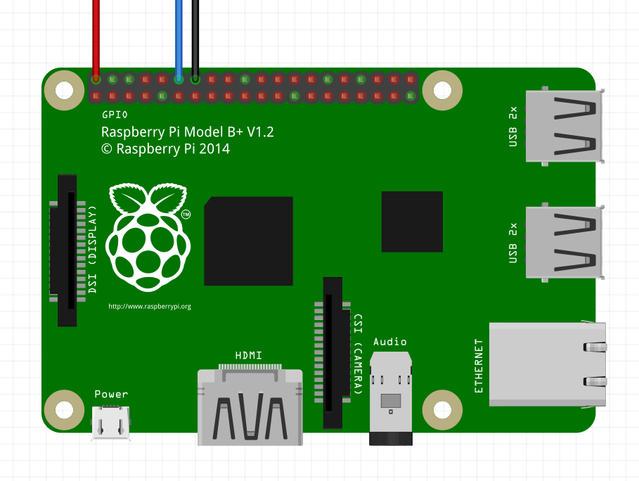
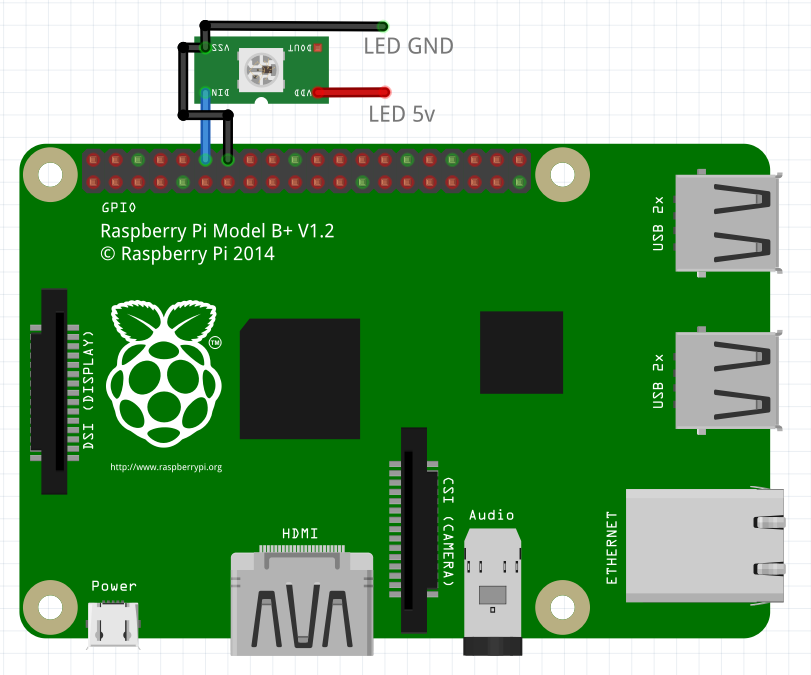
The LEDs should be wired into the Raspberry Pi while it is powered down to reduce the chance of fatal mistakes (always rewire with a computer powered down as they are very sensitive to electrical shocks and the GPIO pins are wired directly into the inner gubbins of the main chip). Wiring is as follows, where the red wire goes to +5v, the blue wire to data and the black wire to ground (there are two on the suggested LED part which is useful when using separate power supplies for the Raspberry Pi and the LEDs).

Raspberry Pi LED Wiring

The WS2812B LEDs are only borderline able to be driven from 3.3v to the data pin (the Raspberry Pi does this). While this is true, with short wires I have never had an issue. I will detail how to use a MOSFET to increase the data signal voltage to 5v later.

I will assume you have a clean install of Raspbian on the SD card in the Raspberry Pi. Before doing anything else, ensure you run the following command in a terminal :

sudo apt-get update

This updates the database of software on the Raspberry Pi and ensures that you’re requesting the latest versions of programs.

Next run the following commands in a terminal :

sudo pip3 install rpi_ws281x

sudo pip3 install adafruit-circuitpython-neopixel

The first time I ran these commands, I had an error for an unknown reason. I ran them again and everything installed properly.

First Test

To make sure everything is working, enter the following program into your favourite text editor on your Raspberry Pi and save it as test.py in a new folder (creating a new folder in the current directory : mkdir <foldername>, switch into the new folder : cd <foldername>, editor suggestion : nano test.py).

#!/usr/bin/env python3
# The line above tells the Raspberry Pi that we want to run this
#   script in Python 3 - so we don't have to tell it later

import board
import neopixel
from time import sleep

# An example program that cycles through Red, Green Blue and then stops

LEDcount = 8

pixels = neopixel.NeoPixel(board.D18, LEDcount)

#red
pixels.fill((100,0,0))
sleep(1)
#green
pixels.fill((0,100,0))
sleep(1)
#blue
pixels.fill((0,0,100))
sleep(1)

# and off
pixels.fill((0,0,0))

If you’re powering the LEDs from the Raspberry Pi, do not turn on too many. 8 is likely to already be too many as they use up to 60mA each (480mA for 8!). To limit power in these examples, I’m not using full brightness (full brightness would be 255 in the first test program), limiting the number of lit LEDs or am only using single colours at a time. For white light and full brightness on all LEDs – use an external power supply if you have more than one or two LEDs! Thanks to PJRC for actually doing some measurements.

Once entered and saved, from a terminal in the saved file’s directory, enter the following command to give the file permission to execute as a script :

chmod +x test.py

“chmod” is the permissions modification command and I think of “+x” as meaning “plus executable”.

We’re ready to run our test – with everything connected, run the following command in the terminal :

sudo ./test.py

If everything goes to play, you should see the connected LEDs cycle through red, green and then blue before turning off. If you see any errors, google is your friend. Also check that you ran the command while in the correct directory, and have permission to use the sudo command.

Make a “Clear” Script

A useful script to make at this stage is a “clear” script. This means if you interrupt another script, or create a script that leaves LEDs on and you want to get rid of them, you can run this script to tidy them up.

#!/usr/bin/env python3
import board
import neopixel
import sys

# assume a default 200 LEDs
LEDcount = 200

# handle parameter
if len(sys.argv) == 2:
   # we have been passed a parameter - this should be the number of LEDs
   LEDcount = int(sys.argv[1])

pixels = neopixel.NeoPixel(board.D18, LEDcount)

pixels.fill((0,0,0))

As before, enter the program, save it with a name (clear.py for example) and then make it executable with chmod. This script can be used in two ways – if you note the “handle parameter” if statement, by using a parameter when running the script you can define how many LEDs you would like to clear. If no parameter is passed, the script assumes you have 200. Note that overestimating is not an issue and so 200 will clear any number up to 200. If you have 201 LEDs, the final LED will remain lit!

To use the script you’ve just entered, type the following at the command line :

sudo ./clear.py

This will clear the first 200 LEDs. To clear a specific number of LEDs (for example, the first 4 of 8 LEDs or if you have 450 LEDs) :

sudo ./clear.py 4

sudo ./clear.py 450

Preparing an Image

Creating the Image we’ll be using to control the LEDs is fairly trivial if you are familiar with any painting programs. The more basic the painting software, the easier the creation! The only complication is making sure that you save in the correct file format (24bit bitmap “.bmp”). Note that I previously tested JPEGs, but found that the compression made black not equal 0,0,0 and so LEDs would be visibly lit when I didn’t want them to be.

For demonstration, I will use GIMP to create my image, because it is free.

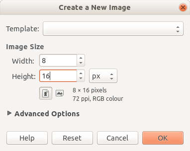
  1. Launch GIMP and create a new image. Make it as wide in pixels as the number of LEDs you have connected (8 for me) and as tall as the number of frames you’d like (16 for me).

    New Image
    New Image
  2. Fill the drawing area with black (RGB 0,0,0).
  3. Zoom in lots until you can see individual pixels and start painting. The pencil (individual pixel drawing tool) is probably best for this. In GIMP you need to change the pencil “brush” size to 1px.
  4. Draw your picture.
  5. Once done, to save in GIMP, select “Export As…” from the File menu.

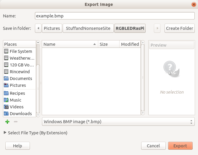
    Export Image
    Export Image
  6. Name your file, pick a location, select “Windows BMP image” and click Export.

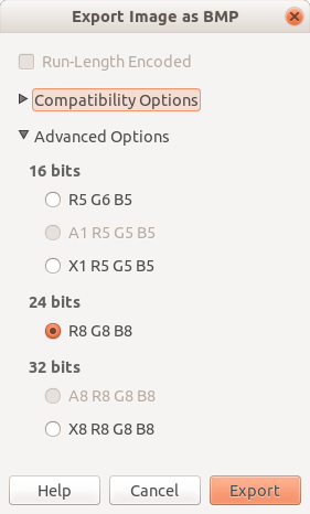
    Export Options
    Export Options
  7. Select “24 bits” under “Advanced Options” in the Export Image as BMP dialog box which appears.

I have created the following example.bmp. Note the red graduated tint in the lower half (only between 0 and 80 out of 255 intensity, which will be significantly more pronounced on the LEDs). I have uploaded the actual file (the following image has been enlarged to make it visible) and it can be downloaded from here (right click and select “Save link as…”).

Example
Example

If you have drawn your image on a computer other than your Raspberry Pi, you will want to transfer it. There are many ways of doing this, from USB drive, to email. I will be using a built in tool command line tool available on Linux and MacOS called “scp”.

In this example, we are assuming that the image file is saved in a folder called “To Transfer” in your home folder on your desktop / laptop computer (aka “the source”), is called “example.bmp”, that the network name of your Raspberry Pi (aka “the destination”) is still the default “raspberrypi”, the username is the default “pi” and that you want to move it to a folder in the Raspberry Pi home directory called “RGBLED”.

If you haven’t consciously changed the network name from “raspberrypi”, it will still be this – if you have, use the new name instead. You can see the network name in the command prompt on the Raspberry Pi if I remember correctly, it is the bit after the “@” symbol).

To move the file from the source to the destination, enter the following command on the source computer :

scp ~/To\ Transfer/example.bmp pi@raspberrypi.local:~/RGBLED/

You will be asked for your Raspberry Pi password (the destination, not the source) and you should almost instantly see the file as 100% sent and the source returns to the standard command prompt. If there is an error, make sure that the source and destination are on the same network, the file paths are correct at both ends, the password is correct and that you haven’t made any typos. If you still have issues, there are websites available that will take you through the process more carefully if you search for “transferring files to a Raspberry Pi using scp”.

In later examples, I will assume that the file “example.bmp” is located in the ~/RGBLED/ (also known as /home/pi/RGBLED/) folder on the Raspberry Pi.

The pictureLED.py Script

The main python script which converts an image into a sequence of LED based patterns is as follows, or can be downloaded directly from here (right click and select “Save link as…”). I recommend placing it in the same “~/RGBLED/” folder on the Raspberry Pi.

#!/usr/bin/env python3

#******************
#* pictureLED.py - convert bmp image into LED sequence Code
#* https://elephantandchicken.co.uk/stuffandnonsense
#* Circuit :
#* Connect LED ground to both the Raspberry Pi ground and the LED power supply's ground
#* Connect LED data to pin D18 (if not boosting with MOSFET)
#* Connect LED +V to the LED power supply 5V
#* Do not mix 5V and 3.3V!
#* If in doubt, details of the circuit and software for controlling from linux
#* are on my website
#*******************

import sys
import board
import neopixel
from PIL import Image

from time import sleep

# Edit the following line if red and green are backwards
switchColours = false

def fixColour(colour, scale):
    # correct the colour order for my ws2812 LEDs and scale the brightness
    # correct colour by switching [0], [1] and [2]
    theResult = (int(scale*colour[0]/100),int(scale*colour[1]/100),int(scale*colour[2]/100))
    if switchColours:
        theResult = (int(scale*colour[1]/100),int(scale*colour[0]/100),int(scale*colour[2]/100))
    return theResult

if len(sys.argv) == 1:
    print("You've not provided any details! Command format is <required> [option] : sudo pictureLED.py <image.bmp> [fps] [loop? 1/0] [loopdelay] [brightness percent] [pin]")
    quit()
if len(sys.argv) > 1:
    # identify image file - use defaults for all other parameters
    imgfile = sys.argv[1]
    fps = 15.0
    maxIntensity = 100
    pin = 18
    loopimg = True
    loopDelay = 0
if len(sys.argv) > 2:
    # set the fps
    fps = float(sys.argv[2])
if len(sys.argv) > 3:
    # loop?
    if sys.argv[3] == "1":
        loopimg = True
    else:
        loopimg = False
if len(sys.argv) > 4:
    # loop delay (at the end of each cycle)
    loopDelay = float(sys.argv[4])
if len(sys.argv) > 5:
    # set a maximum LED intensity and scale all values
    maxIntensity = int(sys.argv[5])
if len(sys.argv) > 6:
    # parameter 5 - set pin for neopixel data
    pin = sys.argv[6]
im = Image.open(imgfile)
pix = im.load()
pixw = im.size[0]
pixh = im.size[1]
print("Image size = ",im.size)
PIXEL_NUM = pixw

if pin==18:
    pinName = board.D18
    # add other options here
else:
    pinName = board.D18

pixels = neopixel.NeoPixel(pinName, PIXEL_NUM, auto_write=False) # pin, number of LEDs

stat = True

while(stat):
    for y in range(0, pixh):
        for x in range(0, pixw):
            pixels[x] = fixColor([pix[x,y][1],pix[x,y][0],pix[x,y][2]],maxIntensity)
        pixels.show()
        sleep(1/(fps))
    sleep(loopDelay)
    stat = loopimg
pixels.fill((0,0,0))
pixels.show()

The program is not actually that large, with the majority of it being a clumsy decoding of the various parameters sent by the user when they execute the command. For a fixed application, much of this could be removed to produce something like the following (untested) code :

#!/usr/bin/env python3

#******************
#* fixedPictureLED.py - convert bmp image into LED sequence Code
#* https://elephantandchicken.co.uk/stuffandnonsense
#* Circuit :
#* Connect LED ground to both the Raspberry Pi ground and the LED power supply's ground
#* Connect LED data to pin D18 (if not boosting with MOSFET)
#* Connect LED +V to the LED power supply 5V
#* Do not mix 5V and 3.3V!
#* If in doubt, details of the circuit and software for controlling from linux
#* are on my website
#*******************

import sys
import board
import neopixel
from PIL import Image

from time import sleep

#################
# Define the image path here!
imgfile = "/path/to/the/image.bmp"
#################

# Other parameters :
fps = 15.0
maxIntensity = 100
pin = 18
loopimg = True
loopDelay = 0
switchColours = false

def fixColour(colour, scale):
    # correct the colour order for my ws2812 LEDs and scale the brightness
    # correct colour by switching [0], [1] and [2]
    theResult = (int(scale*colour[0]/100),int(scale*colour[1]/100),int(scale*colour[2]/100)) 
    if switchColours:
        theResult = (int(scale*colour[0]/100),int(scale*colour[1]/100),int(scale*colour[2]/100)) 
    return theResult

im = Image.open(imgfile)
pix = im.load()
pixw = im.size[0]
pixh = im.size[1]
print("Image size = ",im.size)
PIXEL_NUM = pixw

if pin==18:
    pinName = board.D18
    # add other options here
else:
    pinName = board.D18

pixels = neopixel.NeoPixel(pinName, PIXEL_NUM, auto_write=False) # pin, number of LEDs

stat = True

while(stat):
    for y in range(0, pixh):
        for x in range(0, pixw):
            pixels[x] = fixColor([pix[x,y][1],pix[x,y][0],pix[x,y][2]],maxIntensity)
        pixels.show()
        sleep(1/(fps))
    sleep(loopDelay)
    stat = loopimg
pixels.fill((0,0,0))
pixels.show()

Note the “auto_write=False” parameter passed when generating the “pixels” object. This changes the library’s behaviour so that it only sends updates to the LEDs once the function “pixels.show()” is called.

As before, once you have pictureLED.py saved (pictureLED.py specifically as fixedPictureLED.py is just an example application) on the Raspberry Pi, run the chmod command to allow the file to be executed.

Running the pictureLED.py Script

To run pictureLED.py, open a terminal with the current directory matching the location of both pictureLED.py and example.bmp. The command format is as follows :

sudo ./pictureLED.py <filename.bmp> [fps] [loop? 1/0] [loopdelay] [brightness percent] [pin]

Parameters between “<>” are required and parameters between “[]” are optional, although all preceding optional parameters are required. These are two example commands :

sudo ./pictureLED.py example.bmp

sudo ./pictureLED.py example.bmp 2 0 0 50

The first example uses all default settings (15 fps, loop, zero second loop delay (time before the pattern repeats), 0% brightness reduction and the default pin) on the image “example.bmp”. The pattern will repeat indefinitely – to stop it, press Ctrl-c.

The second example passes a number of parameters, more specifically describing how we want the program to run. In this example, we run at 2 fps, not looping, zero second loop delay, at 50% of full brightness. Note we do not specify the pin – this is because pin D18 is currently the only available pin in my code.

Running at Boot

A simple way to make your LED sequence run when the Raspberry Pi powers on (note, powers on, not when you log in) is to edit the operating system file “/etc/rc.local”. Absolute care should be taken, as if you make a mistake, the Raspberry Pi will not finish booting. Assuming that the absolute path (from the root level of the disk, not from the Home (aka “~”) folder) for pictureLED.py is “/home/pi/RGBLED/pictureLED.py”, enter the following command in a terminal :

sudo nano /etc/rc.local

A file will open in the text editor nano. Use the arrow keys to scroll to the bottom of the file. The last line should be “exit 0”. Above this enter the following new text :

/home/pi/RGBLED/pictureLED.py /home/pi/RGBLED/example.bmp 2 &

There are a number of things to note here.

  • All paths have to be absolute as this means that they are always correct, no matter where the current directory is when the script executes.
  • “sudo” is not needed because the parent script is already executing with root permissions.
  • As shown it is best (don’t not do it) to include a ” &” (that is a space followed by an ampersand). This tells the computer to run the script as a background process and means that if your script throws and error, or stops to wait for user input, the computer does not hang but keeps booting. It also means that the computer doesn’t wait for your script to finish before continuing (imagine we used the default “loop” option).
External Power Supply

To drive more LEDs at full brightness, connect the LEDs to an external 5v power supply, remembering to connect the ground between both the LED power supply and the Raspberry Pi (not doing so can damage the Raspberry Pi or LEDs as connecting the grounds holds both devices to the same reference point and avoids the voltages floating between the two supplies, potentially causing high voltages where there shouldn’t be). The following shows a suggested wiring :

External Power LED Wiring

Do not connect the 5V to the Raspberry Pi (unless you know what you are doing, and it is the only power supply to the Raspberry Pi (i.e. there is no micro USB connected)).

Remember that each LED could draw up to 60mA and ensure that your selected LED power supply is able to provide sufficient current to power all of your LEDs. Given that the supply is at 5v, this means you are looking for 5×0.06 = 0.3 watts per LED. For example, if you had 100 LEDs, you would need a power supply rated to at least 30 watts at 5v.

5v Data Signal

Another potential issue which has not impacted me, is due to the Raspberry Pi sending data to the LEDs at 3.3v. I believe that the minimum voltage required by the LEDs when running at 5v is 3v and 3.3v does not give much overhead. This is likely to result in issues when longer wires result in a further reduction in voltage, potentially causing intermittent issues or complete failure to operate.

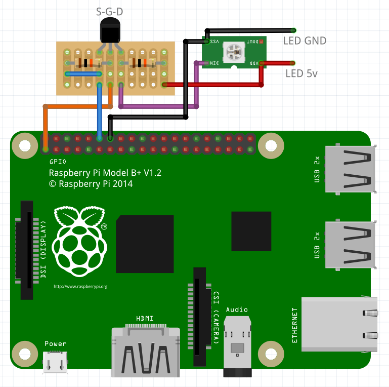
This can be solved by voltage shifting the Raspberry Pi output using a MOSFET. The following method is actually a way of getting bi-directional level shifting (very useful for I2C), but is simple enough that we might as well use it here. I’ve based the circuit on the one here : http://www.hobbytronics.co.uk/mosfet-voltage-level-converter, please double check that my implementation is correct! Note the strip board could be smaller in reality (you could manage a 4×3!), but I couldn’t get Fritzing to show stood up resistors.

MOSFET LED Wiring
MOSFET LED Wiring

Note that the orange wire is connected to a 3.3v pin on the Raspberry Pi. As labelled, the pinout for the 2N7000 MOSFET is Source, Gate, Drain from left to right, with the flat on the package facing you.

Future Project

The next thing I’d like to do is write a program to allow me to draw animations for an n by n LED matrix and save them in this image format. It shouldn’t be too difficult and would be fun and interesting. I don’t have a significant sized LED matrix though – I think the biggest I have is only an 8×8.

Aluminium Raspberry Pi Case


I recently picked up a new case for my raspberry pi from Banggood.

RPi Case 1

The case is machined aluminium and very well made. It came with a pitft compatible 2.2 inch screen which plugs directly into the GPIO port. It also provides six buttons connected to GPIO pins, an infrared receiver and a I2C port. There is a clear plastic screen protector and all spacers and screws provided, including an allen key. I expect the case works with the Raspberry Pi 2 and 3 (which I am using).

RPi Case 1

Setting with a Raspberry Pi 3

Mechanically, assembly is simple enough. The only tricky bit might be getting all the buttons in place as they are not retained in any way until everything is brought together. Remember to take the protective film off both the screen and the clear plastic screen protector.

The software setup process isn’t immediately obvious on the banggood page, but someone has asked a question and received a couple of answers which help. There are various links to pre-made images which I was unable to download due to permissions and / or dead links (random third party images aren’t my preferred source of OS images anyway) the manual instructions are usable for the most part though and I was able to get the screen running following these instructions.

I will repeat them here just in case the other website goes down – the following is confirmed to work on a Raspberry Pi 3 running Jessie, although it did not prove possible to rotate the display by changing the angle in config.txt. I already had a newer version of the GPIO software and so didn’t bother installing their recommended version.

Update the OS.

sudo apt-get update
sudo apt-get upgrade
sudo apt-get dist-upgrade

Make sure required software is installed. Ensure that the GPIO software is newer than their suggested version (0.5.11).

First run apt-get to install gcc, pygame and python-dev. I suspect these will already be installed. If they are, there is nothing to worry about, apt-get will just pass over them.

sudo apt-get install gcc python-pygame python-dev

Next, lets find what version of the GPIO software we have:

find /usr | grep -i gpio

This will list installed software in the /usr folder containing the text “gpio” and should give a clue to the version. Running on one of my Pis, the following are the first few lines of output :

/usr/lib/python2.6/dist-packages/RPi.GPIO-0.6.2.egg-info
/usr/lib/python2.6/dist-packages/RPi/_GPIO.so
/usr/lib/python2.6/dist-packages/RPi/GPIO

This tells me that I have version 0.6.2 installed – newer enough I think!

Next, make sure that SPI and I2C are both enabled. To do this, I will use the raspi-config tool rather than directly editing the settings file as they do in the original instructions :

sudo raspi-config

On the following screen, select option 8, “Advanced Options”.

raspi-config

In the Advanced Options menu, select option A6, “SPI”.

raspi-config-spi

Select “Yes”.

raspi-config-spi2

Do the same for I2C by selecting Option 8 again, then option A7 (instead of A6) and selecting “Yes” to enable I2C.

Press the right arrow key on the home menu to select “Finish” and exit the program. You might be asked to restart the machine, I wouldn’t bother for now although it isn’t an issue if you do.

Enter the following command to open the file config.txt in the text editor nano.

sudo nano /boot/config.txt

Once the file is open, scroll to the end and append “dtoverlay=pitft28-resistive, rotate=270 speed=48000000 fps=30” excluding quotes (and all on one line). I have tried adjusting rotate=270 to other values, but it hasn’t changed the console display. I haven’t tried this while running the GUI, where it might make a difference.

To make the console appear on the display it is necessary to edit the file cmdline.txt. We also take this chance to change the font to make it more visible on the small screen.

sudo nano /boot/cmdline.txt

With this file open, we add the text “fbcon=map:10 fbcon=font:VGA8x8 ” (excluding quotes) just before the word “rootwait”. It might be necessary to scroll to the right with the right arrow key to find the text.

Reboot (sudo reboot) and it should all work.

Other things to discuss at some point…

Setting Up the GUI

Working with the Buttons

Not Used IR Yet

Screen faults, new screen, smaller buttons.

Shutdown and restart python. False triggering.

Reduced wifi range. Access to GPIO – possibly counter with I2C.

Screen and splitscreen. Run at boot.

Bits and Bobs

Lots of of things arrived from China this week, most interesting thing is a number of lithium polymer battery charger boards from here…

Battery Charger

I’m planning to use this as part of the power supply for arduino projects. This provides the ability to re-charge a 3.7v lithium ion battery of the type used in my quadcopters. I’ll then run the output terminals into a DC-DC converter, when they arrive, to get a steady 5v. The inspiration for this is in part from this interesting article, although I had ordered the chargers before I spotted it.

Lithium ion batteries do not like staying empty so it is probably sensible to stick a potential divider and monitor the battery voltage. When The voltage gets too low, it should be possible to shut down the circuit. For now, I’ve wired in a JSP connector (correct me if it isn’t, I find it difficult to find out exactly what connectors are called). While charging, a bright red LED is lit, once the device finishes charging, the red LED is extinguished and a blue one lights instead. I’ve checked the voltages on the batteries after charging, but haven’t done any substantial testing yet.

Battery Charging

I also got a number of other things at the same time – I got some more breadboard, because you can never have enough, a Raspberry Pi breadboard breakout, because I gave one of mine away the other week, some new little breadboard power supplies, because they looked like a better design than my existing ones, some SNES style USB controllers and some battery boxes.

Breadboard PSU

My existing breadboard power supplies cover quite a few rows of contacts. They also do not appear to supply enough current for my Z80 computer project, but as these new ones use the same regulator (AMS1117), I’m unlikely to have the same issues. It might have been something I was doing – I’ll investigate again at some point in the future.

Raspberry Pi Breakout

These Raspberry Pi breadboard breakouts are great for working with the GPIO on the Raspberry Pi without too much faff. I have used them for projects where I have no intention of making any custom boards – I do have the stuff to make up my own ribbon cables and have IDC board connectors, so this is always an option if I want to make something smaller.

Battery Box

Putting batteries into project boxes in a way that an end user will be able to change them without too much fuss has always been an issue for me. I really don’t like how project boxes cost as much as all the electronics held within, nor do I like that the ones with battery compartments cost three times as much. This is my attempt at finding a solution. Sadly, I’m trying to move away from 9v batteries, because they’re not really the best solution.

USB Controller

Hours of fun – I have now bought eight of these in total. Four to give away to colleagues at work who have recently obtained Raspberry Pis, and four of my own. These work straight out of the box with the Retro Pie image. Retro Pie boots straight into Emulation Station, with the bulk of the setup done for you. Unfortunately, it still takes a while to get ROMs sorted etc. but there isn’t really anything they can do about that without breaking the law! The Raspberry Pie 2 is able to run emulators up to and including the N64 and original PS, although I find it is really best at the SNES and various Nintendo handhelds.

BeebEm and Marathon in RetroPie

I’ve been setting up an SD card for my Raspberry Pi 2 with the latest stable version of RetroPie. RetroPie is a collection of emulators presented from a single interface that can be navigated easily with a controller. BeebEm is a BBC Micro emulator, and is not included as standard in RetroPie.

As I, and several of my friends grew up with BBCs, I decided that this needed sorting and so following these instructions, I was up and running in no time. I also added Marathon 2 and Marathon Infinity into the “Ports” section, using the method shown here. This second method is a lot simpler, but is only really suited to single games, rather than whole platforms with multiple games. For some reason, the original Marathon game did not work properly (loaded, but would not enter a game). I will return to look at it another time.

For those who do not know, the Marathon games were a series of games produced by Bungie in the 1990s (after Pathways into Darkness and Gnop, before Oni and Halo, at a similar time to the Myth series!). The games were fun to play, good to look at and had well written story lines. A rare thing at the time. Just before Microsoft bought Bungie, they kindly released the source to the Marathon engine and so a community project (called Aleph One)was born to update it and port it to new platforms. This is how, years down the line, I am able to play the games on a computer the size of a pack of cards, running on a processor derived from the follow on of the BBC Micro, using an operating system that it was never released for.

Marathon Infinity
Playing Marathon Infinity on the Raspberry Pi