Lego Control Lab Interface – Serial Cable Woes

Lego Control Lab Interface – Serial Cable Woes

If you have a Lego Dacta Interface B (AKA Control Lab or 9751) but don’t have the original cable, you might have trouble talking to it. The reason for this is that RX and TX are wired backwards compared to what you’d normally expect. Even more confusing, the gender of the RS232 port on the interface is female, which isn’t normally the case for this wiring.

Getting the Right Cable

Buying an Original Cable

If you’re buying to connect to a standard RS232, 9 pin port on a PC, you’ll want Lego part number 9768-1.

If you’re buying to connect to a vintage Mac with RS422 ports, you will want Lego part 9769-1.

Lastly, if you’re buying for an Acorn Archimedes computer, you’ll likely want Lego part 9768-1 (the PC part).

Making a Cable

If you’re making your own cable, you’ll need to keep in mind that the pinout of the port on the interface is described as follows in the manual :

The connector on the back panel is male and you only need the three pins shown to be connected for everything to work.

Using a Null Modem Adapter

If you’re using a standard serial cable instead of one wired for the Control Lab interface, or using a USB to RS233 adapter, you’re going to need a null modem adapter, but one with a male plug on one end and a female plug on the other.

Making Your Own Adapter

I made my own using two ribbon cable RS232 9 pin D Sub connectors from eBay. It is a little fiddly, but a fairly cheap solution. As mentioned above, the interface doesn’t actually use most of the pins (such as flow control) so you only actually need three wires.

In your adapter, connect…

  • Pin 5 to Pin 5
  • Pin 2 to Pin 3
  • Pin 3 to Pin 2

You should end up with something that looks like the following…

Buying an Adapter

Most adapters look like the following, but it can be tricky identifying what is a null modem adapter and what is just a pass through or gender changer, so take care. Lately these adapters have been more expensive than I would expect.

You must buy one that is wired as a null modem adapter, and has one male and one female connector.

Alternatively, there are adapter cables available, which is what I most recently purchased.

Again, you must ensure that the cable is a null modem adapter, and that it has one male and one female end.
A Couple of Clone Arduino Linux Issues

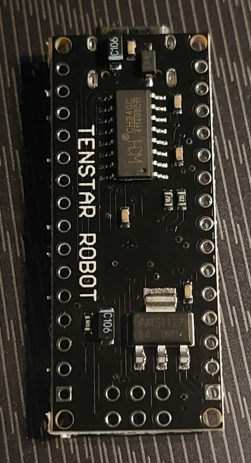
A Couple of Clone Arduino Linux Issues

The serial port appears for a single second, and then vanishes before you can upload any code.

This has been happening to me with Pop OS, but apparently also happens with other Ubuntu variants. I can’t believe what the cause is, but if you check dmesg and you will possibly find the following occurring :

[   98.044600] usb 3-2: New USB device found, idVendor=1a86, idProduct=7523, bcdDevice=81.33
[   98.044606] usb 3-2: New USB device strings: Mfr=0, Product=2, SerialNumber=0
[   98.044607] usb 3-2: Product: USB Serial
[   98.046052] ch341 3-2:1.0: ch341-uart converter detected
[   98.046409] usb 3-2: ch341-uart converter now attached to ttyUSB0
[   98.608979] input: BRLTTY 6.4 Linux Screen Driver Keyboard as /devices/virtual/input/input41
[   98.887664] usb 3-2: usbfs: interface 0 claimed by ch341 while 'brltty' sets config #1
[   98.888541] ch341-uart ttyUSB0: ch341-uart converter now disconnected from ttyUSB0

What we see happening is the OS finds the newly plugged in CH340 based serial device on your board and creates a new serial port, in my case, ttyUSB0. Excellent. But then, along comes “BRLTTY”. BRLTTY has decided it knows what this device is, removes the serial port and turns the device into an input / keyboard device. BRLTTY apparently knows best and claims all devices with the manufacturer / product ID of a USB to UART adapter chip, that is absolutely not always the product they think it is. This is really poor default behaviour, especially as this all happens silently. Apparently BRLTTY is accessibility software for the blind that is installed by default.

To solve the issue, assuming you’re not blind, simply type “sudo apt remove brltty” (without quotes) at the command line and it will be uninstalled, making the issue go away.

Not in Sync

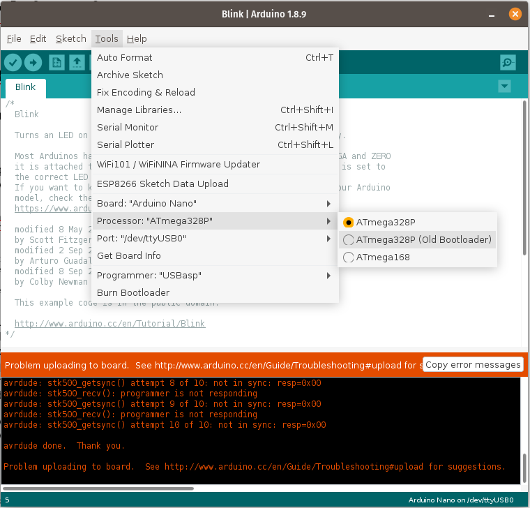
The not in Sync error, where you get a repeated message such as the following :

avrdude: stk500_getsync() attempt 1 of 10: not in sync: resp=0x00

… is an old one with many causes. One cause now seems to be that if you use a clone device, the Arduino IDE refuses to talk to it by default. The solution might be to change the “Processor” in the Tools menu to “ATmega328P (Old Bootloader)”. This would apply to boards such as Unos and Nanos. This might actually also apply to older genuine Arduino Boards.

As you might guess, I’ve had a slightly frustrating day. All I did was try to load a program into a clone board someone gave me the other day.

Lego Power Functions Connector Pinout

Lego Power Functions Connector Pinout

The Lego Power Functions electrical system replaced the older 9v system used on the Interface B (AKA Control Lab or 9751) and RCX, for connecting motors and in a small number of instances, sensors. The new connector retained the nominally 9v rating, but was no longer possible to rotate to change polarity. To solve this, reversing switches are available, and the most common battery box has a three position switch with both polarities as well as off.

The main advantage of the Power Functions connectors is that they carry an unswitch 9v power bus as well as the traditional reversable control signals. The permanent 9V is used to power the IR receiver, and is always passed through an IR receiver even when outputs are off. I suspect sensors also used the permanent 9v to power their circuitry without interruption.

This is a significant advantage over the older 9v system where sensors used to have to harvest and store power in a capacitor with the input port being momentarily switched to a different mode to recharge the capacitor and keep the sensor powered.

The Pinout

The Power Functions pinout is as follows.

It can be seen that the outer two pins have fixed voltages regardless of the polarity of the orange switch, while the pins labelled A and B (conventionally called C1 and C2, but I was unsure which was which) are swapped depending on whether the orange switch is in position 1 or position 2.

With the connector oriented with the two knobbles / studs at the top, numbering contacts from left to right, 1 is always ground, 4 is always 9v, and 2 & 3 are switchable so that one is 9v (or a reduced power signal when using an analogue controller) and the other 0v. When powered, but with no direction signal (for example plugged into a powered IR receiver, but with no buttons pressed on the basic remote), both 2 & 3 are at 0v.

With this battery box, the third central position of the orange switch completely turns off the power to all pins.

9v to Power Functions Adapter Cables

Warning! When making adapters between Power Functions and 9v, you must not connect the outer two contacts on the Power Functions end. This could/will result in a short.