When you power on your smart relay (which is loaded with my Firmware) for the first time, an LED will light immediately – when you see this, press the button “L1”, or the only button if there is just one button and hold it for 5 seconds (or a bit longer to be on the safe side).
If you get a laptop with Wifi and look for available networks, you should see a new network starting with “Sonoff”. Connect to this – the default password is “password”.
Write down the name of this network as we will need it later.
Once connected, open a web browser and go to the following URL :
To connect your relay to the house wifi, continuing from above (with a computer connected to the relay’s own “Sonoff” wifi network), carefully enter the following URL, substituting <ssid> for the name of your wifi network.
http://192.168.4.1/wifi?ssid=<ssid>
For example, if your wifi network is called “spaceship” then you would enter http://192.168.4.1/wifi?ssid=spaceship
Next, to tell the relay the password for your wifi network, carefully enter the following, substituting <passwd> for your wifi password :
http://192.168.4.1/wifi?password=<passwd>
If you now power cycle the relay (do not press the button), it should automatically connect to your wifi network and be available to all devices on the network. Note that if your network name or network password contains symbols which are not valid in a URL, you might need to use escape characters, change the wifi details, or give up.
Using the wifi network name you wrote down earlier, try the following, replacing <relayname> with the network name you wrote down :
http://<relayname>.local/set?data=1010
and this :
http://<relayname>.local/set?data=0101
If these do not work, try the same, without “.local”.
From the Terminal
From the terminal on a Mac or Raspberry Pi, try typing the following command
wget -qO – http://<relayname>.local/set?data=1111
This command can be called from inside Linux style bash scripts. Similar things can be done from within Python.
A few years ago I bought myself a ReadyNAS Duo. I really like the thing – it has a steel case, rubber feet, three USB ports for external hard drives and printers and a gigabit ethernet port. I liked it so much I also bought my father one. Early on, I modified mine to allow root SSH access and it was actually the machine I learnt a lot of my Linux skills on. SSH can be enabled using the add-on listed here on the official Netgear site.
A few years later, I spotted an article on the internet which discussed upgrading the RAM in a ReadyNAS Duo, as the machine has a laptop style SODIMM slot. As the RAM was now effectively “old”, second hand prices on eBay were extremely tempting, and so I decided to upgrade the original 256MB of RAM. Given that there were hardly any price differences between 512MB and 1024MB, I decided to go for the full Gigabyte of RAM. The part arrived and I installed it, it was recognised and everything was good. Interestingly, a while later I read more and discovered that lots of people have trouble performing this upgrade and many products with the correctly specification simply do not work or are unreliable. Seems I was lucky.
Fast forward further few years and I mentioned the RAM upgrade to my dad and we agreed that it would be interesting to upgrade his as well. I did some digging and re-discovered the issues people had. I decided to give it another go and ordered a couple of SIMMs from Hong Kong, where the second prices were lower for two than they were for one in the UK. The parts actually arrived in 7 days, which was better than I was expecting. Before giving a SIMM to my dad, I’ve decided to test it in my own ReadyNAS. Should you want to do something similar, the following should help.
Why More RAM?
There isn’t a huge benefit to upgrading the RAM in your ReadyNAS Duo. There may be small speed increases, but the main reasons I’ve done so are :
It will allow me to run more other Linux software in the background, as long as it isn’t excessively processor intensive.
It is not very expensive, with the upgrade costing approximately £3.50.
Because I can, and that is often reason enough.
Ordering the RAM
For the upgrade, you will need the following RAM:
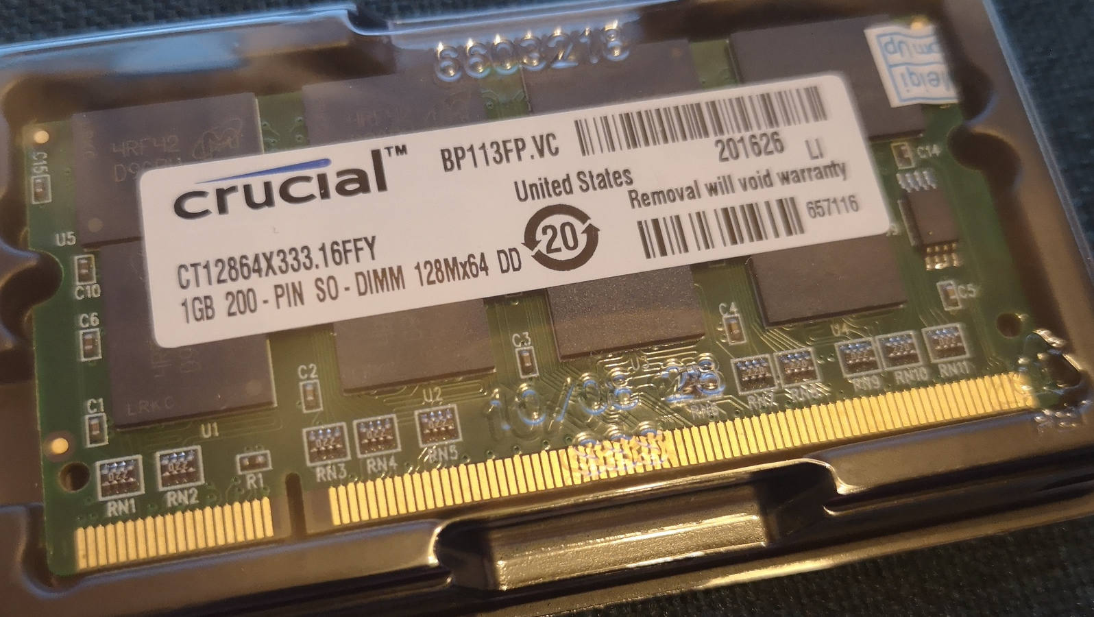
PC2700 DDR333MHz SODIMM RAM module.
512MB or 1024MB (1GB).
2.5-3-3-7 specification
Some luck
Micron/Crucial RAM
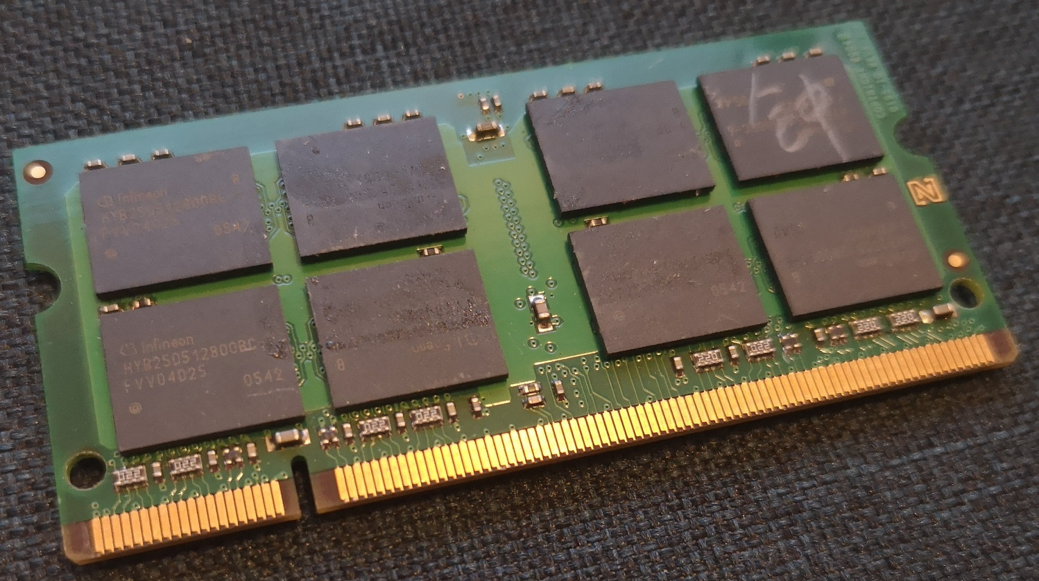
I seem to have had luck with an unidentified 1GB SIMM using Infineon chips, and a 1GB Crucial (probably) SIMM using Micron chips. The RAM I’m testing today was purchased from the eBay seller galaxyshoppingcn in Hong Kong. The listing is currently still available here, but obviously this wont last forever. Current price is £6.66 for a pair of SIMMs.
Infineon RAM
Opening the case.
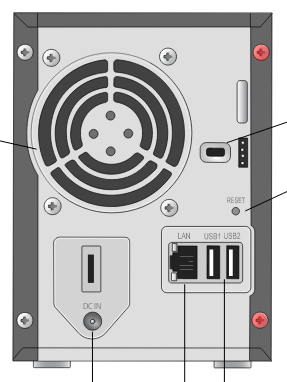
To access the RAM slot on the ReadyNAS Duo, it is necessary to remove the two right hand screws highlighted in red in the following picture (borrowed from the manual).
Screws to Remove
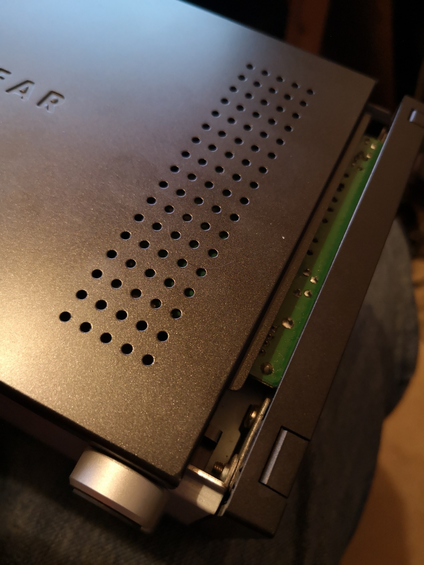
Once these have been removed and stored safely, carefully place the ReadyNAS on its side on a soft surface with the long side face closest to the two screws facing upward. Place one hand flat on the long side face and hold the rest of the unit with the other. Push backwards (towards where the screws were removed from) on the long face and it should clunk backwards about 10mm or so with intermediate force. This side panel is very similar to traditional PC case side panels and so you should now be able to lift it off, exposing a single, occupied SODIMM RAM slot.
Mind the Gap
Removing the existing RAM
At the two ends of the RAM slot are silver coloured retention leavers. At the same time, push the end of the silver leavers away from the RAM SIMM until it releases and stands up further from the socket.
Released RAM
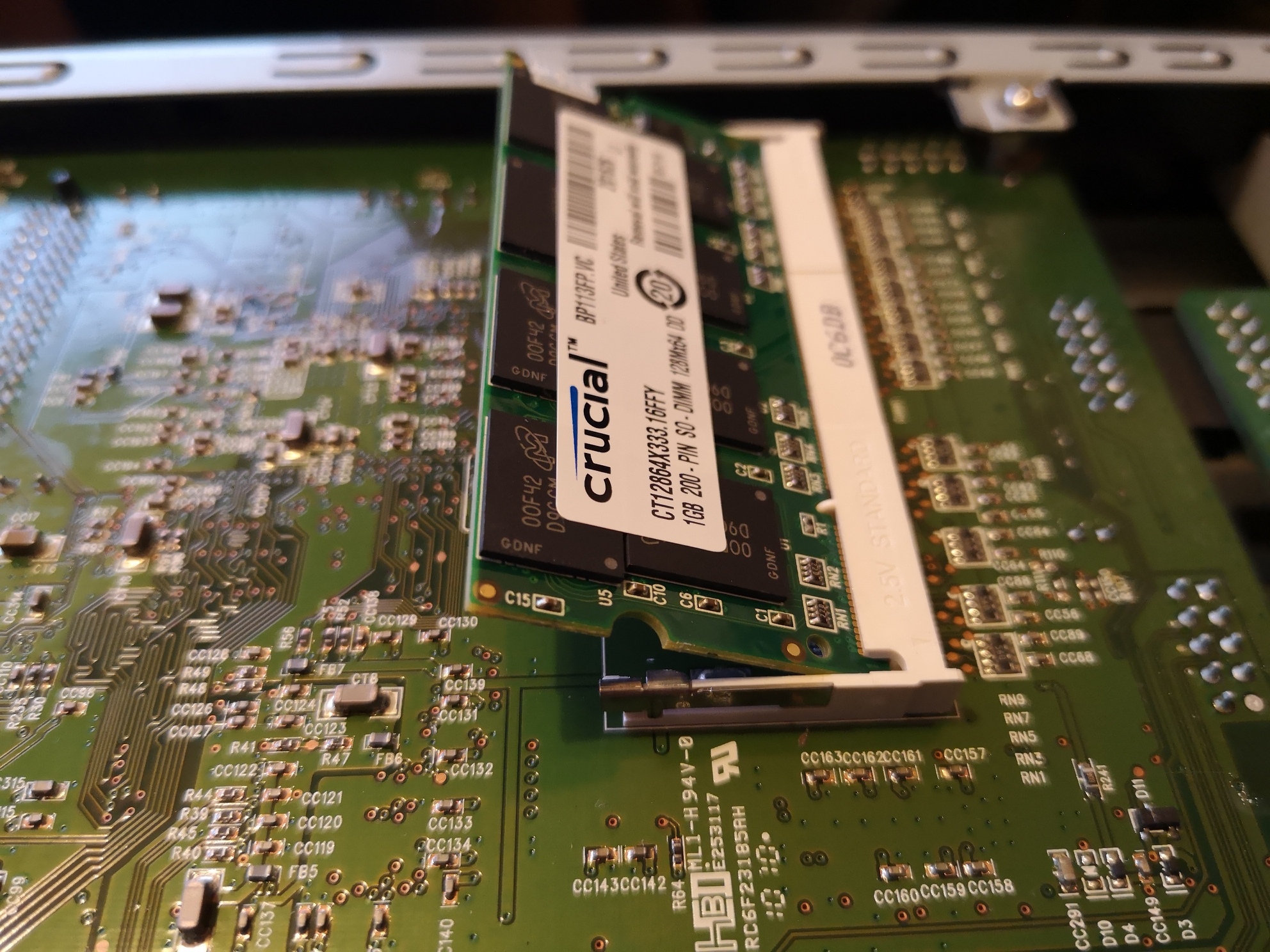
Take particular note of how the RAM sits in the socket at this point – the angle, and how much of the root of the RAM is within the socket. Note that the contacts on the edge of the RAM are almost hidden.
It should now be possible to withdraw the RAM SIMM. Avoid touching anything other than the edges of the (usually) green PCB and look after the SIMM as it is the only one you have which is guaranteed working!
Installing new RAM
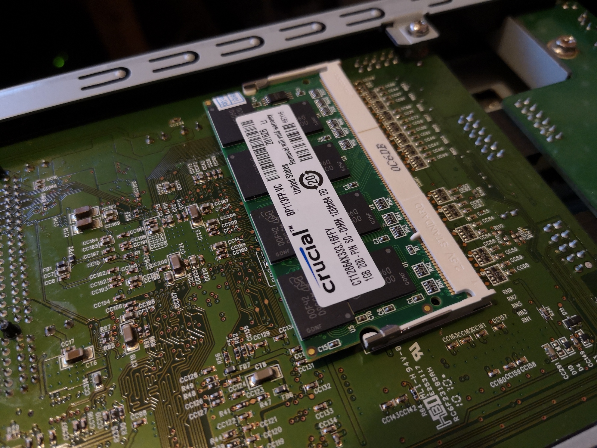
Take your new, higher capacity RAM SIMM and place it in the socket in the ReadyNAS. Place it at the same angle as the previous SIMM was after you released it, taking notice of the alignment notch about one fifth of the way along the SIMM. Ensure that it is fully seated in the slot – this may require some pressure – the gold contacts are usually almost invisible when it is properly seated. Also see the “Released RAM” image above.
Once you are satisfied, push the highest edge of the RAM down so that it becomes parallel with the socket. It should click slightly at both ends as the latches slot home. If it presents any significant resistance, ensure that it was seated properly and try again. Consider fully removing and re-seating.
RAM in the Slot
Closing the case
Place the removed side panel back in the location from where it was lifted off – approximately 10mm from the closed position. For reference, see the photo above titled “Mind the Gap”. Once it is sat flush, firmly close it back to its home position.
Depending on how confident you are of success, you could either re-install the screws now (taking care not to cross-thread them), or wait until testing is finished.
Checking that it is recognised
Connect an ethernet cable to your ReadyNAS, connect power and turn on the device as usual. Wait until all lights have stopped flashing and log into the device admin page as you usually do (for example http://192.168.1.2/admin if that is your ReadyNAS network address). If the ReadyNAS does not successfully boot, firstly ensure that the new RAM SIMM is correctly installed and try again, and then give up, re-install the original RAM (ensure /that/ still works) and go back to eBay to find another SIMM.
Home Screen
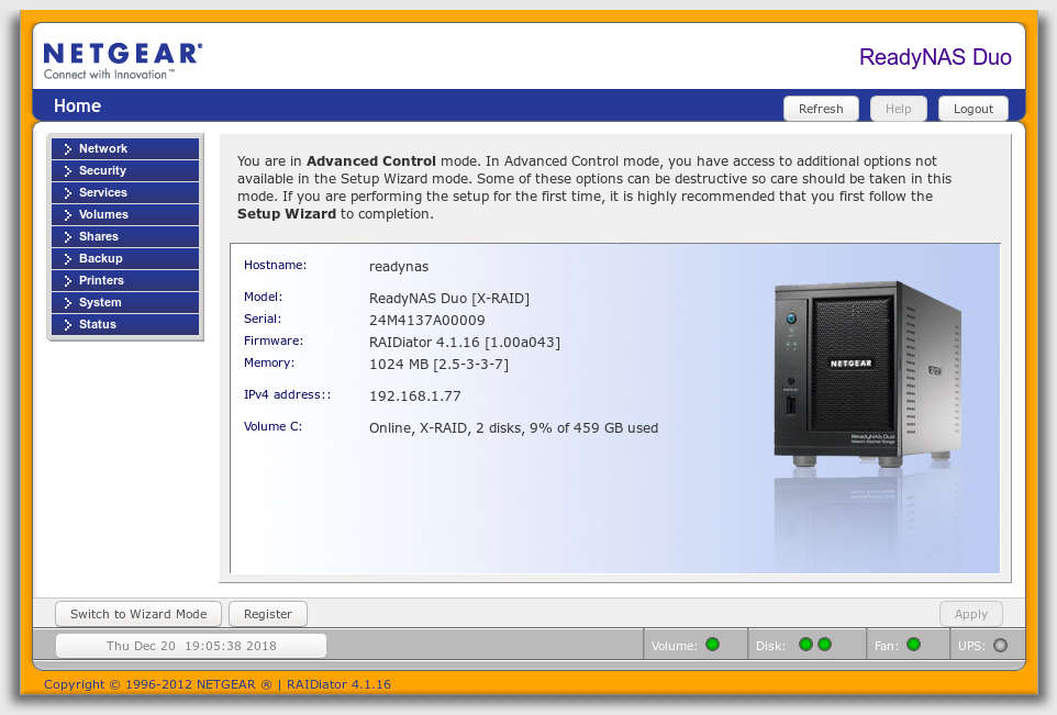
If everything is looking good at this stage, on the admin home screen, you should see reference to 1024MB of RAM and the string of numbers “2.5-3-3-7”. This means that the RAM is fully recognised and that it is running at the correct speeds.
Running a full memory test
Between this, and this websites, I put together how to undertake a full memory test and what to expect to see.
Starting the Memory Test
Note that the memory test will take a substantial amount of time, during which the fan will run at full speed. Only run the test if you have the time to leave it. For me, the test took approximately an hour and a half.
With the ReadyNAS Duo turned off, press and hold the power button without obscuring the two hard drive activity lights. You will be holding this button for approximately 25 seconds. Watch the pair of activity lights, after 5 seconds they will briefly flash – after the 5th flash, release the power button. The power button should continue to blink and initially you should see just the left light lit of the pair of activity lights. The fan will continue at full speed through the test.
Understanding the Lights
During the test, the power button will blink for the entire period. As the memory test goes through each of eight steps, the two activity lights will progress through the following pattern :
1-0, 0-1, 1-1, 0-0, 1-0, 0-1, 1-1, 0-0
Once finished, the third, single, central green status light will illuminate, with the two disk activity lights lit and the power light flashing… if successful. If the two disk activity lights are flashing, the memory test has failed.
The ReadyNas Duo will remain in this state indefinitely (useful if you run the test unattended). Poking the power button restarts the ReadyNAS.
If you have not already done so, re-install the case screws.
For the last long while, I’ve been tracking the temperature in our conservatory. This started when we had a pigeon living in there and I realised it was getting very warm during the day. Firstly, I started tracking the temperature, then I added a fan to an existing catflap to help cool the area, (then I removed the pigeon) and ultimately, the system now runs on an ESP8266 which monitors the temperature, switches the fan on for low and high temperatures (drawing air from the more thermally moderate house), provides a web interface for control and generates a status webpage using dynamically created SVG images.
Temperature Plot
An Orange Pi Nano computer is scheduled to fetch these images over the internal network every now and then, and uploads them to my website. I have been also saving the resultant 24 hour plots for each (most – I’ve had a couple of power and or internet outages) day.
Historic data is crudely stored here (I need to add pages, possibly automatically because I’m lazy. I think I worked out how at the time (show number ranges x through y, multiples… something like that. Perhaps need to learn how to pass parameters to php as I don’t really do internet stuff), but never implemented it.
In the future, I plan on modifying the code to reduce the work done by the ESP8266 to just fan control and temperature logging, with more of the intelligence / image generation offloaded to the Orange Pi Linux SBC. I will then consider creating more sensor nodes, using sleep functions to minimise power consumption to a level suitable for battery and / or solar power and ultimately, put other sensors around the house and in the garden shed.
Temperatures in the house might enable me to control our central heating boiler in a more intelligent fashion than it already is, while the garden shed would be a good source of the ambient temperature in our location (handy for passive cooling with ambient air for example, using fans fitted to the fresh air bricks in the house).
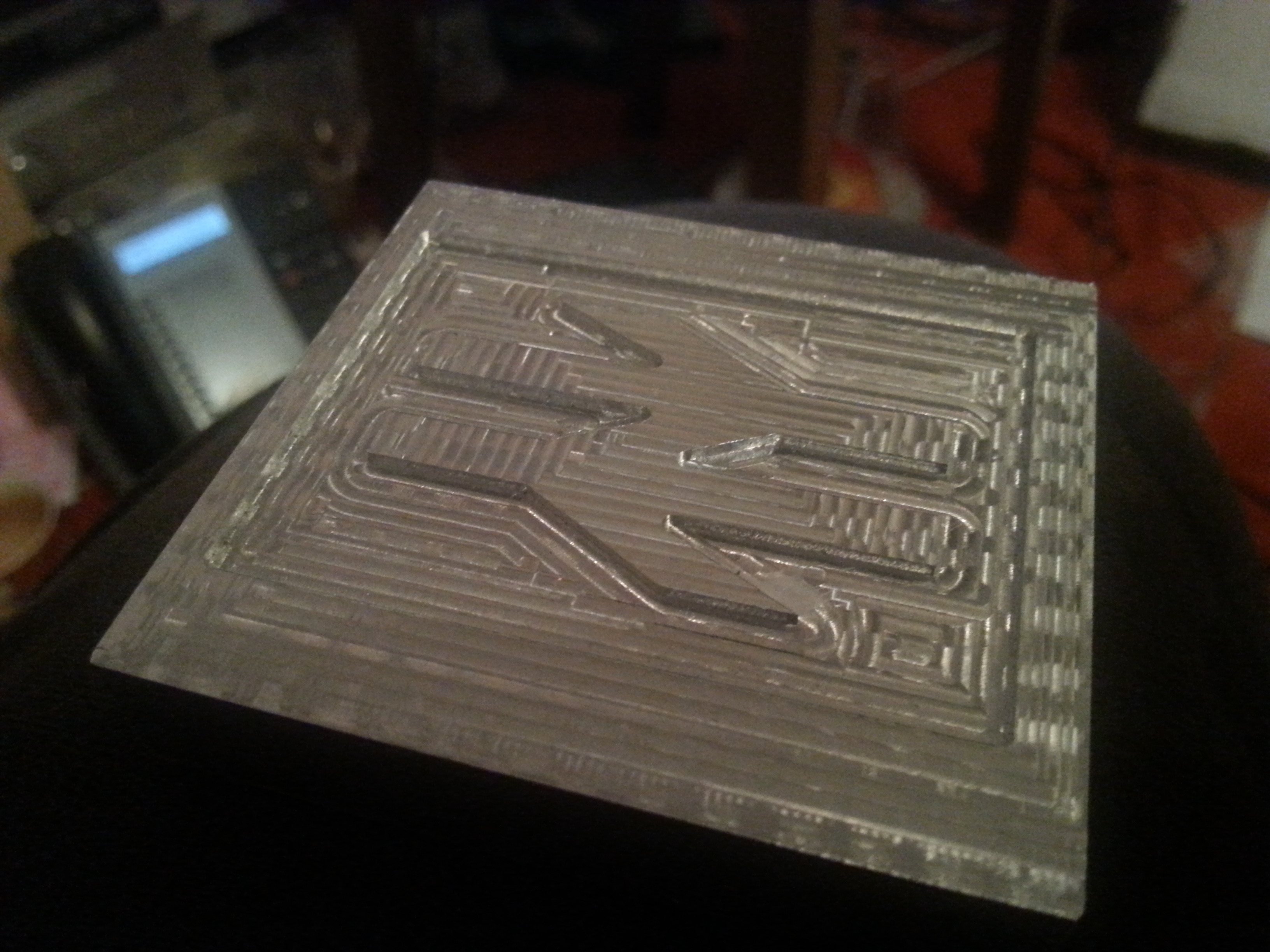
A couple of old photos of things I managed to cut on my small Chinese CNC router from Aluminium. The first is the “Arrows of Indecision” (the British Rail and later National Rail logo), the second a pair of gears. Note the gear centre is slightly out of position on one gear as I accidentally set the cut order incorrectly and cut the hole after the outside, and the part moved.
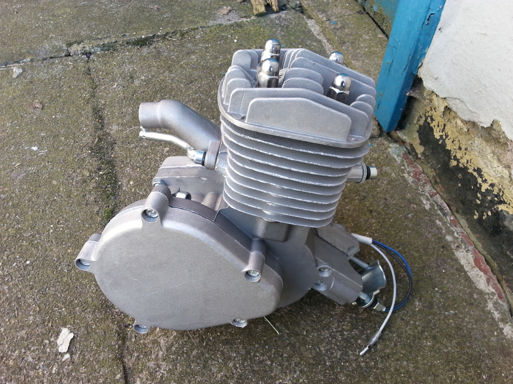
I’ve purchased a small engine which I plan to make a remote control car with. Sadly I keep getting distracted, but it should be an interesting project.
I wanted to build a “petrol-electric” car, but I figure I can’t afford the alternator, power electronics and motor needed to handle the 3kW or so output from the engine. Seems chains and belts are good value for money sadly. Here are some photos of the engine.
While on holiday last month we took a trip to the Peak Wildlife Park, which turned out to be a great day out, despite the rain. I took a number of pictures of the very friendly “wild”life. We also went to the National Space Centre.
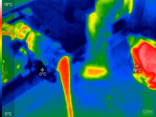
Last year I went on a trip to France to undertake some testing – we brought a small Seek thermal camera with us which proved very useful. The following is a picture of some heated water flowing into the very cold room.