68008 SBC LCD Control

68008 SBC LCD Control
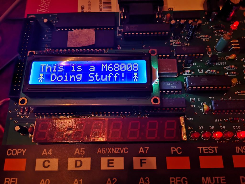
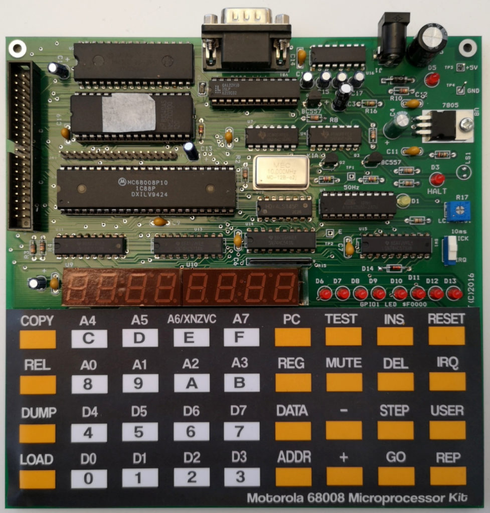
The following is my first attempt at controlling the LCD on my Wichit Sirichote (URL updated 2024 to new website) Single Board Computer. Please forgive any terrible programming as I’m not very familiar with assembly language, and even less so with 68k assembly language programming. I’ve tried to make the code a little modular so the subroutines can be re-used. I previously described the software setup I’m using to program the board from Linux here. There are two versions of the same program (almost) in this post, the second of which animates the little stickman using interrupts for timing.

; Hardware Locations in Memory
gpio1		equ	$f0000		; LED PORT
lcdcw		equ	$60000		; LCD command WR
lcddw		equ	$60001		; LCD data WR
lcdcr		equ	$60002		; LCD command RD
lcddr		equ	$60003		; LCD data RD

; LCD Commands
lcdbsy		equ	$80		; LCD BUSY
lcd8bt		equ	$38		; Select 8 bits interface
lcdinc		equ	$06		; Entry Mode - Increment
lcddcb		equ	$0E		; Display On, Cursor On, Blink OFF
lcddnc		equ	$0C		; Display On, Cursor Off, Blink Off
lcdoff		equ	$08		; Display Off, Cursor Off
lcdclr		equ	$01		; Clear Display
lcd1st		equ	$80		; Set first line start
lcd2nd		equ 	$C0		; Set second line start

; Program location in memory
		org 	$400		; start of program

START
		move.l	#stack,a7	; sure
		move.w	#$2100,sr	; what these do
		bsr 	subinit		; initialise LCD
		bsr 	subcust		; send little man
		bsr 	subclr		; clear screen
		bsr 	subrow1		; go to home address
;send text
		lea	text1,A2	; get address of text string
		bsr 	subsend		; send the text located at A2
		bsr 	subrow2		; go to second line
		lea 	text2,A2	; next line text address
		bsr 	subsend		; send it
loop		jmp	loop		; forever

; ---------------------------------------------------

sublcdr	; wait for lcd ready
		movem.l	D0-D1,-(sp)
		move.w	#$ffff,D1
lcd_bu0
		move.b	(lcdcr),D0
		andi.b	#lcdbsy,D0
		beq.s	lcd_bu1
		dbra	D1,lcd_bu0
		moveq	#1,D1
lcd_bu1
		movem.l	(sp)+,D0-D1
		rts

subinit ; set up the display
		move.b	#lcd8bt,(lcdcw)	; write command $38 - 8 bit mode
		move.b	#lcd8bt,(lcdcw)
		move.b	#lcd8bt,(lcdcw)
		bsr	sublcdr		; wait for ready
		move.b	#lcdinc,(lcdcw)	; write command $06 increment cursor
		bsr	sublcdr
		move.b	#lcddnc,(lcdcw)	; display on, cursor off, blink off
		rts

subclr	; clear the display
		bsr	sublcdr		; wait for ready
		move.b	#lcdclr,(lcdcw)	; write command $01, clear display
		rts

subrow1	; go to first line
		bsr	sublcdr
		move.b	#lcd1st,(lcdcw)	; write command $80, first line start
		rts
	
subrow2	; go to second line
		bsr	sublcdr
		move.b	#lcd2nd,(lcdcw)	; write command $C0, first line start
		rts
	
subsend	; send string that starts at A2, and ends with zero
		movem.l	D0,-(sp)
ss1		bsr	sublcdr
		move.b	(A2)+,D0
		beq.s	senddone
		bsr	sublcdr
		move.b	D0,(lcddw)
		bra ss1			; blt next
senddone
		movem.l	(sp)+,D0
		rts

subcust	; create and send a custom character
			bsr	sublcdr
			move.b	#$48,(lcdcw)	; custom char 0 edit
			lea man,A2		; send data for man (note, can't have 0 in data)
			bsr	subsend
			rts

; string to display, terminating with zero
text1		dc.b	'This is a M68008',0
text2		dc.b	1,' Doing Stuff! ',1,0	; 1 gives special char 1. (a little man)
man			dc.b	%01110,%01110,%00100,%01110,%10101,%00100,%01010,%01010,0

ram	ds.b	32		; not sure
stack		equ	*	; what these do

This second version uses interrupts for timing a simple animation, but there is more code that I do not understand in it, so please forgive me if there are non-critical errors. The code isn’t very efficient in its use of data registers.

; Hardware Locations in Memory
gpio1		equ	$f0000			; LED PORT
lcdcw		equ	$60000			; LCD command WR
lcddw		equ	$60001			; LCD data WR
lcdcr		equ	$60002			; LCD command RD
lcddr		equ	$60003			; LCD data RD

; LCD Commands
lcdbsy		equ	$80			; LCD BUSY
lcd8bt		equ	$38			; Select 8 bits interface
lcdinc		equ	$06			; Entry Mode - Increment
lcddcb		equ	$0E			; Display On, Cursor On, Blink OFF
lcddnc		equ	$0C			; Display On, Cursor Off, Blink Off
lcdoff		equ	$08			; Display Off, Cursor Off
lcdclr		equ	$01			; Clear Display
lcd1st		equ	$80			; Set first line start
lcd2nd		equ 	$C0			; Set second line start

; Program location in memory
		org 	$400			; start of program

START
		move.l	#service_level2,$68	; not
		move.l	#stack,a7		; sure
		move.w	#$2100,sr		; what these do
		move.b	#$0,d2
		move.b	#$0,d3
		move.b	#0,d4
		bsr 	subinit			; initialise LCD
		bsr 	subcust			; set up little man in char 1 & 2
		bsr 	subclr			; clear screen
		bsr 	subrow1			; go to home address
;send text
		lea	text1,A2		; get address of text string
		bsr 	subsend			; send the text located at A2
loop		cmpi.b	#1,d4			; Don't re-send if you've already done so
		bge	loop			; loop if already shown
		bsr	subrow2			; pre-move to the start of the second line
		cmpi.b	#1,d3		
		blt	alt			; go to alt if d3<1
		lea 	text2,A2		; send text2
		bsr 	subsend			; send it
		move.b	#1,d4
		bra	loop
alt		lea	text3,A2		; send text3
		bsr	subsend
		move.b	#1,d4
		bra	loop			; forever - note jmp is an absolute address, bra is rel

; ---------------------------------------------------

service_level2
		addi.b	#1,d2		; increment d2
		cmpi.b	#50,d2		; check if d2 is 50 or more
		blt	skip		; rte if not 50
		clr.b	d2		; reset d2 to 0
		move.b	d3,gpio1	; debug code - shows status on leds
		clr.b	d4		; reset "don't send again" value
		addi.b	#1,d3		; increase d3 (which line 2 to send)
		cmpi.b	#2,d3		; check if d3 is too big
		blt		skip	; if it isn't, finish
		clr.b	d3		; if it is, make it = 0
skip		rte			; return

sublcdr	; wait for lcd ready
		movem.l	D0-D1,-(sp)
		move.w	#$ffff,D1
lcd_bu0
		move.b	(lcdcr),D0
		andi.b	#lcdbsy,D0	; check if the lcd is busy
		beq.s	lcd_bu1
		dbra	D1,lcd_bu0
		moveq	#1,D1
lcd_bu1
		movem.l	(sp)+,D0-D1
		rts

subinit ; set up the display
		move.b	#lcd8bt,(lcdcw)	; write command $38 - 8 bit mode
		move.b	#lcd8bt,(lcdcw)
		move.b	#lcd8bt,(lcdcw)
		bsr	sublcdr				; wait for ready
		move.b	#lcdinc,(lcdcw)	; write command $06 increment cursor
		bsr	sublcdr
		move.b	#lcddnc,(lcdcw)	; display on, cursor off, blink off
		rts

subclr	; clear the display
		bsr	sublcdr				; wait for ready
		move.b	#lcdclr,(lcdcw)	; write command $01, clear display
		rts

subrow1	; go to first line
		bsr	sublcdr
		move.b	#lcd1st,(lcdcw)	; write command $80, first line start
		rts
	
subrow2	; go to second line
		bsr	sublcdr
		move.b	#lcd2nd,(lcdcw)	; write command $C0, first line start
		rts
	
subsend	; send string that starts at A2, and ends with zero
		movem.l	D0,-(sp)
ss1		bsr	sublcdr
		move.b	(A2)+,D0
		beq.s	senddone
		bsr	sublcdr
		move.b	D0,(lcddw)
		bra 	ss1					; blt next
senddone
		movem.l	(sp)+,D0
		rts

subcust	; create and send a custom character
		bsr	sublcdr
		move.b	#$48,(lcdcw)	; custom char 0 edit
		lea 	man,A2		; send data for man (note, can't have 0 in data)
		bsr 	subsend
		rts

; --------------------------------------------------------


; string to display, terminating with zero
text1		dc.b	'This is a M68008',0
text2		dc.b	2,' Doing Stuff! ',1,0	; 1 gives special char 1. (a little man)
text3		dc.b	1,' Doing Stuff! ',2,0	; 2 gives special char 2. (a little man arms up)
man			dc.b	%01110,%01110,%00100,%01110,%10101,%00100,%01010,%01010,%01110,%01110,%10101,%01110,%00100,%00100,%01010,%01010,0

ram	ds.b	32		; not sure
stack		equ	*	; what these do
68k SBC Programming on Linux

68k SBC Programming on Linux

Having grown up using computers based on Motorola’s 68k family of microprocessors, I have been considering trying to build a simple 68k processor computer of my own. Given how long it took me to get around to build a breadboard Z80 computer, and with a growing sense that I really should learn how to program a GAL or CPLD to reduce the chip count… I decided to buy one of Wichit Sirichote’s single board computers based on the 68008 processor (URL updated 2024 to new website).

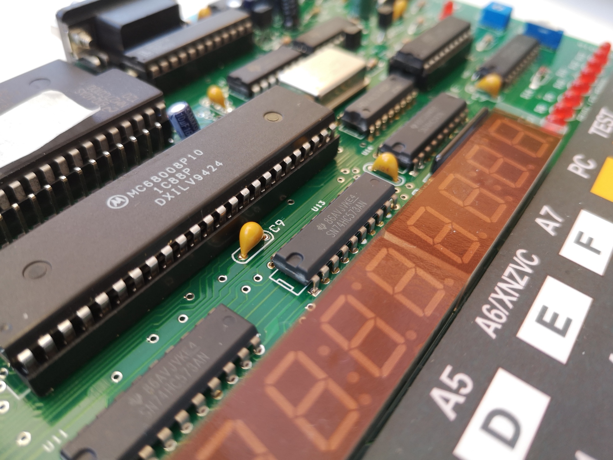
The Motorola 68008 is a slightly odd chip which has 32 bit internal functionality, coupled to an 8 bit data bus instead of the 16 bit data bus of the regular 68000. It was designed to be a cheaper / simpler alternative to the 68000 processor.

The following page details how I got to the point that I could run my own software written on a Debian-ish Linux machine, on the 68008 board.

Step 1 – Get the Assembler and Compile it

I decided to use the vasm assembler. It runs on multiple platforms and can assemble code for a large number of processors including the Z80, 6502 and 68008, all of which are of interest to me for various computers / projects. I downloaded the latest release source, which at the time of writing is v1.8g (locally hosted here).

I extracted the source code into a folder called vasm (using the GUI archive tool because I’m lazy), before navigating to within the folder in a terminal. To decompress from the command line you should use the command “tar -xvf ./vasm.tar.gz” from within the same directory – note this is “-xvf” not “-xvzf” as the file appears to be only a tar and not zipped, but misnamed. Given that I’m running linux, I figured I could use the default make file and so all I had to do was run the command :

make CPU=m68k SYNTAX=mot

This tells the compiler what our target CPU family is, as well as the assembly language syntax / style we plan to use (in this case Motorola, rather than the GCC syntax which is a little different).

Once the compiler had finished building the project, I was able to copy the new program called “vasmm68k_mot” from the current directory to where I wanted to run it from – note I didn’t bother installing it and am just running it from a folder in my home directory.

Step 2 – Writing a Test Program in Assembly Language

Wichit Sirichote’s webpage includes a download of several example programs, which are also listed in the manual. The following simple program loads the number 12345678 into a register (d0) and then displays part of it on the LEDs (memory mapped at f0000). The fist line identifies where in memory the program should be located. A copy of this program in assembly can be downloaded here. This is a text file and can be opened and edited in any text editor.

         org       $400
start    move.l    #$12345678,d0
         move.b    d0,$f0000

I have saved this assembly program as “FirstTest.asm” in the same location that I have placed the vasm application. After a bit of fiddling, I was able to work out the required parameters to assemble my files into a correctly formatted hex file and settled on the format vasmm68k_mot -m68008 -Fsrec -s19 -o <outputfile.hex> <inputfile.asm>. The -Fsrec parameter uses the Motorola S Record output format, with the -s19 parameter using 16bit S Record mode. So, to assemble the FirstTest.asm file into FirstTest.hex, all in the same folder as the vasmm68k_mot application, I use the following command.

./vasmm68k_mot -m68008 -Fsrec -s19 -o ./FirstTest.hex ./FirstTest.asm

This gives the following feedback that doesn’t indicate there were any errors (if you get errors, double check you pointed it to the correct files and didn’t make any typos in your assembly – also, check that tabs are used between columns).

vasm 1.8g (c) in 2002-2019 Volker Barthelmann
vasm M68k/CPU32/ColdFire cpu backend 2.3f (c) 2002-2019 Frank Wille
vasm motorola syntax module 3.13 (c) 2002-2019 Frank Wille
vasm motorola srecord output module 1.0 (c) 2015 Joseph Zatarski
CODE(acrx2):	          12 bytes

Opening the resultant FirstTest.hex file in a text editor shows the following, which is the assembled program in Motorola hex.

S009000073656734303023
S10F0400203C1234567813C0000F00009A
S9030000FC

If you’ve got this far, congratulations, you’ve cross-assembled a 68k program. Now it is time to load your creation into the 68k Computer.

Step 4 – Connecting the SBC to a Computer

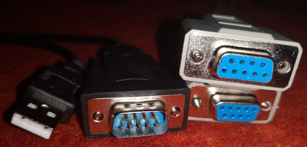
Programs can be loaded directly into RAM on the 68008 board over serial. To connect the 68008 board to a modern computer it is most likely that you’ll need a USB to RS232 adapter, but it is worth noting that since both devices being connected are computers (rather than a computer and a peripheral), both ports are likely to be male. As such, we’ll need a “null modem” cable, which is similar to an ethernet crossover cable in that the TX and RX wires are switched so that you’re not connecting TX to TX and RX to RX. I have been using a cable similar to this linked item, as well as a bodge using a USB to UART and a UART to RS232 adapter to get up and running while I waited for a null modem cable in the post. I have had issues with cheap cables failing in the past and so have ordered a 4 port RS232 box with a USB interface as a replacement. The box hasn’t arrived yet.

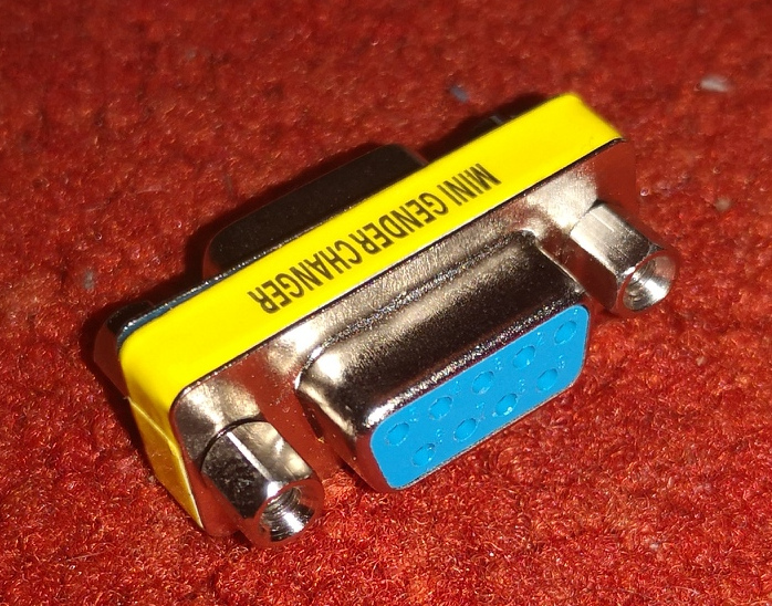
Note it is possible to get “gender changer” adapters which do not cross over the TX and RX pins, meaning that while you can physically connect your computer and the 68008 board, they will not communicate.

Once you have all the right cables, with the 68008 board powered down, connect the null modem cable to the 68008 board and the USB RS232 adapter, plug the USB RS232 adapter into your computer and run the following command.

ls /dev/tty*

There will likely be an item listed as ttyUSB0, or similar. If no serial device is clearly obvious, unplug the USB RS232 adapter and run the command again. Compare the two lists and identify what has changed. This is your serial port. Next, make sure that the software “screen” is installed on your Linux machine by running the following command at the command line and following on screen prompts (either telling you it is already installed and is the latest version, or asking if you would like to install it).

sudo apt install screen

Note that some users on Linux do not have permissions to access serial ports. Running the following command (substituting “MY_USER_NAME” for your user name) and restarting your computer should fix this.

sudo usermod -a -G dialout MY_USER_NAME

Next, run the following command at the command line on your Linux computer (substitute ttyUSB0 for the correct serial port name if you found it to be different earlier).

screen /dev/ttyUSB0 2400

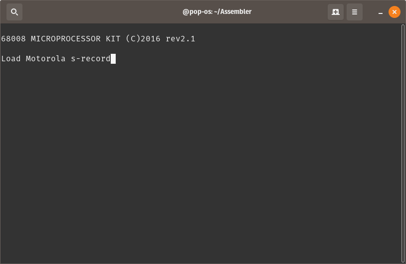
This command connects to the USB RS232 adapter at a baud rate of 2400. Now turn on the 68008 board and you should see the text “68008 MICROPROCESSOR KIT (C)2016 rev2.1” or similar. This shows that communications are working. If you don’t see this, check your connections and cables. Make sure you didn’t have any permissions errors. Try running the “screen” command using sudo.

Step 5 – Loading the Program

Assuming you were able to establish the connection between your Linux computer and the 68008 board, press the “LOAD” button on the 68008 board. You should now see the message “Load Motorola s-record” in the window.

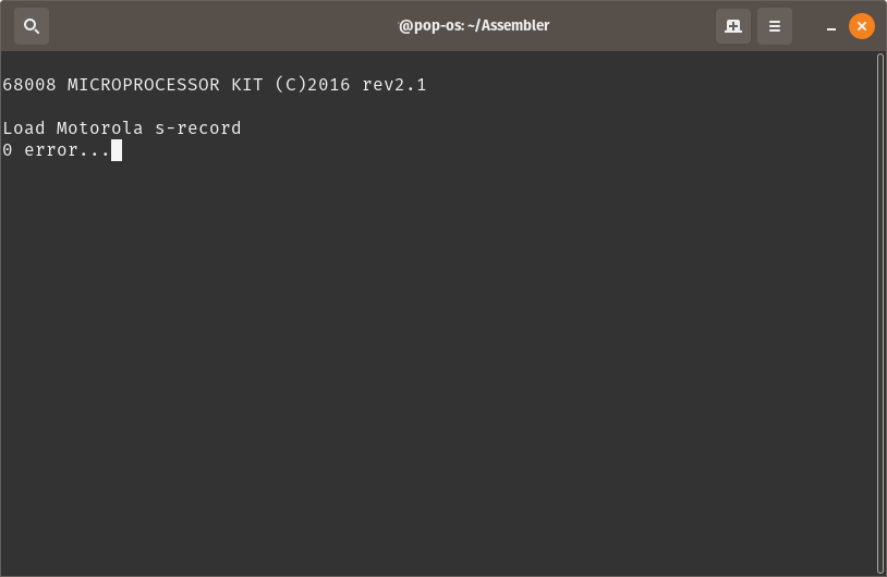
Copy the entire contents of the FirstTest.hex to the clipboard, and then paste the copied text into the terminal window in which “screen” is running (often right click in the terminal window and select the option “Paste”). If everything works correctly, once the program is loaded, you should see a message saying that there were no errors.

Step 6 – Stepping Through the Program

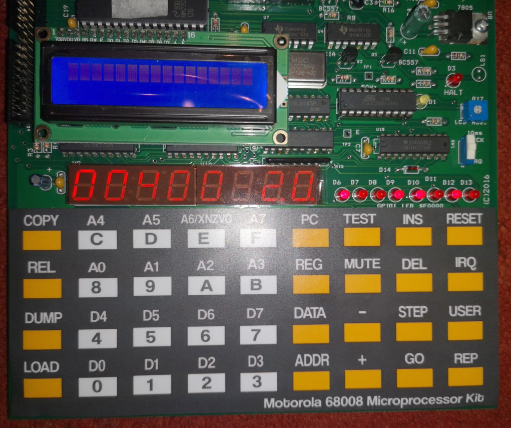
To check that the program is now in memory, press the “PC” button (PC stands for Program Counter) on the 68008 board. If the 7 segment display now shows 00400 20, this is a very good sign. The 00400 is the Program Counter address, where the machine will start running a program from. The “20” is the first byte of the program that was loaded over serial. If it says anything other than “20”, then something isn’t right. Press the “+” key repeatedly, and you should see the following sequence 3C, 12, 34, 56, 78. These are the next few bytes of the program. Press “PC” again to return to the start of your program.

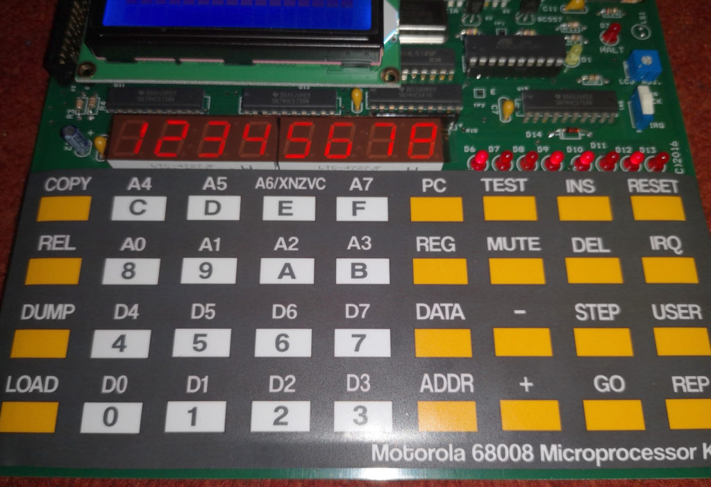
If the “STEP” button is pressed, the 68008 board will execute the first command in the program – in this case, load 12345678 into the register D0. You can check this by pressing the “REG” key, followed by the “0” (zero) key. The 7 segment display should show 12345678. Press “PC” to return to displaying the current location in the program.

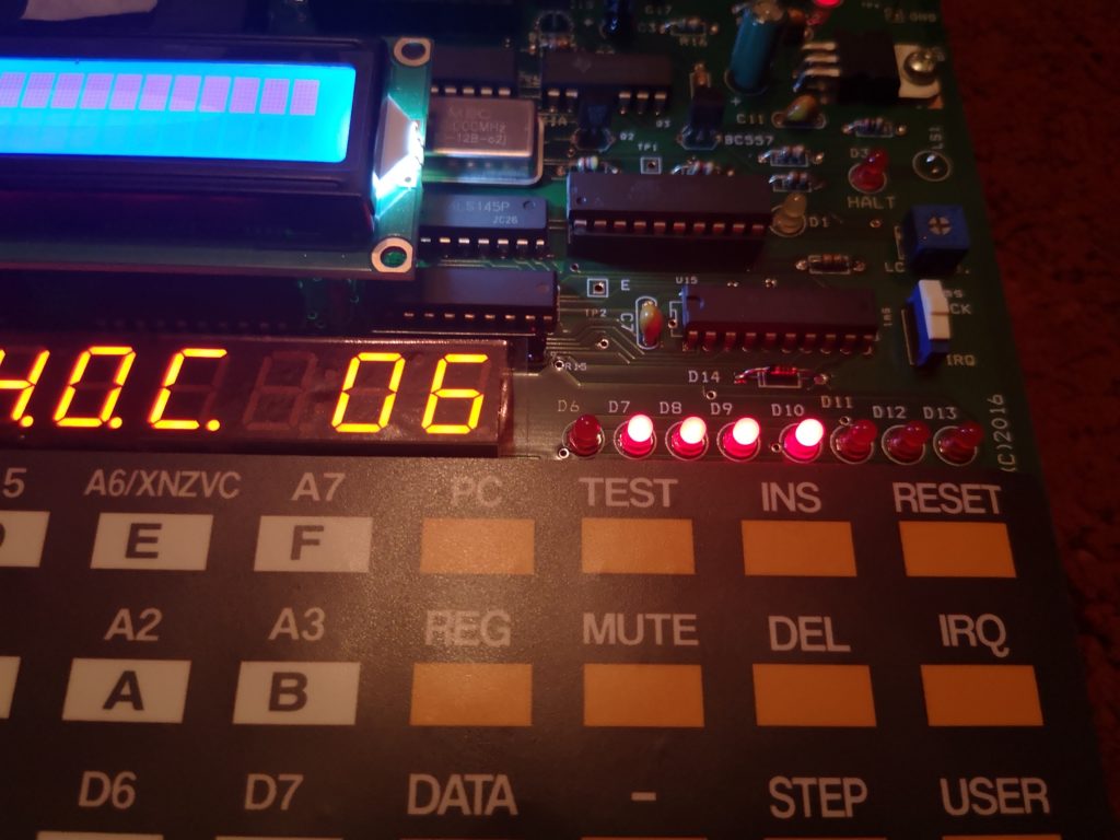
Press “STEP” again, and part of this number will be shown on the eight LEDs on the right hand side of the 68008 board.

Congratulations, you’ve completed loading and stepping through the tiny example program.

Step 7 – Trying Another Program

The following program is based on one of the other provided examples, modified to alternatively flash every second LED, rather than count in binary as the provided example does.

gpio1	equ	$f0000
	org	$400
start	move.l	#service_level2,$68
	move.l	#stack,a7
	move.w	#$2100,sr
	move.l	#$0,d0
	move.l	#$55,d1
here	bra	here
service_level2
	addi.b	#1,d0
	cmpi.b	#20,d0
	blt	skip
	clr.b	d0
	eori.b	#$ff,d1
	move.b	d1,gpio1
skip	rte
ram	ds.b	32
stack	equ	*

The code uses the 10 ms tick feature on the board (a 100hz pulse) and an interrupt to time the changes. The (inverse of the) initial state of the LEDs is set in the line “move.l #$55,d1”. Changing the number #$55 (remember this is in hex as indicated by the “$” sign) will change the initial state of the LEDs. For example, replacing it with #$00 will cause all eight LEDs to flash together.

The speed at which the LEDs flash can be changed by modifying the line “cmpi.b #20,d0”. #20 is (in decimal, as there is no “$” sign) the maximum number the code will count to before changing the state of the LEDs. In the example above, #20 means that when the value in d0 reaches 20, the LEDs will be inverted and d0 will be reset to 0. Otherwise, d0 will be increased by 1 and the program will wait for the next 10ms tick to trigger an interrupt. “service_level2” is triggered each time one of these 10ms ticks occur, otherwise the processor runs in the infinite loop “here bra here”.