Based on the responses from the “ReadSensorTable” command in my Economatics Smart Box SB-04, I’ve concluded that the following official sensor exist :
Index
Name
Val1
Val2
Units
3
Temp range 1
Tmp
Temp
degC
4
Voltage range 1
V
Volts
mV
5
Temp range 2
Tmp
Temp
degC
6
Voltage range 2
V
Volts
volts
7
Temp range 3
Tmp
Temp
degC
8
Voltage range 3
V
Volts
volts
9
Temp range 4
Tmp
Temp
degC
10
Sound (standard)
Snd
Sound
?
11
pH
pH
pH
?
13
Position
Pos
Postn
deg
17
Light (standard)
Lt
Light
?
21
R’Humidity
Hmd
Humid
%RH
22
Sound range 1
Snd
Sound
dbA
23
Light range 1
Lt
Light
Lux
24
Sound range 2
Snd
Sound
dbA
25
Light range 2
Lt
Light
Lux
26
Barometric Pressure
Atm
Atmos
mBars
27
Light range 3
Lt
Light
Lux
28
User adaptor
UA
User
?
29
0-1 Volt adapator
V
Adapt
?
30
Temp (low range)
Tmp
Temp
degC
31
Light gate
LG
LGate
?
33
Temp (standard)
Tmp
Temp
degC
There is more data being fed back by the box regarding these sensor types, but it is a little bit of a pig to understand as my terminal is reading it as escape characters. I suspect it would be easier to understand if I had some official sensors myself. I suspect that some experimentation is in order! I’ll connect a variable voltage to the detection pin and watch what sensor types the box detects at each voltage. With an ADC connected to my computer I might be able to automate the process… but that is probably more effort than it is worth.
Having got a copy of the Economatics Smart Box “Operating System Serial Protocols” document curiosity of John and flaxcottage.com, I noted that one of the commands returns the name of a command based on the provided command number. Given that the instruction manual is most likely for an older version of the Smart Box (mine is an “SB-04”, rather than the older “SB-01”), which is build around a 6502 processor rather than the Mitsubishi microcontroller in mine, I wrote a short program which iterates through every command number between 0 and 99 and returns the “CodeName”. The following table shows the resulting output – I’ve also included room for other Smart Box variants for when I get access to one, or if someone runs the same program for me.
Command No.
SB-01
SB-01/EV
SB-04
0
Blank*
Blank
1
Version
Version
2
Reset
Reset
3
NameCode
NameCode
4
CodeName
CodeName
5
MultipleSetup
MultipleSetup
6
MultipleRead
MultipleRead
7
MultipleServer
MultipleServer
8
IdentSystem
9
Credits
Credits
10
WriteMotors
WriteMotors
11
ReadMotors
ReadMotors
12
MotorForward
MotorForward
13
MotorReverse
MotorReverse
14
MotorHalt
MotorHalt
15
MotorPower
MotorPower
16
PatchMF*
PatchMF
17
MotorVoltage
20
WriteOutputs
WriteOutputs
21
OutputPower
OutputPower
22
GetSensors*
GetSensors
23
CheckSensors*
CheckSensors
25
ReadSensorTable
28
SetBitHigh
SetBitHigh
29
SetBitLow
SetBitLow
30
ReadADCReg*
31
WriteADCReg*
32
ReadACIAReg*
33
WriteACIAReg*
34
ReadVIAReg*
35
WriteVIAReg*
36
SetVIAHigh*
37
SetVIALow*
40
ReadADC
ReadADC
41
ReadADCs
ReadADCs
42
ForcedADCRead
ForcedADCRead
44
HighResADC
HighResADC
45
LowResADC
LowResADC
47
ReadResolution
ReadResolution
50
DownloadData
DownloadData375
52
UploadData
UploadData375
54
ExecuteCode
ExecuteCode375
55
StoreByte
StoreByte375
56
ReadByte
ReadByte375
57
ReadRAMSize
59
ExtendCall
60
SetClock
SetClock
61
ReadClock
ReadClock
62
ReadTopmem
63
WriteTopmem
64
ReadLomem
65
WriteLomem
66
ReadHimem
67
WriteHimem
90
ReadInputs
ReadInputs
91
ReadBit
ReadBit
92
ReadOutputs
93
CountReset
94
CountRead
Items marked with a * in the SB-01 column are undocumented. The SB-01 commands were taken from a machine belonging to mph1708 on the stardot.org.uk forums. The machine was running ROM OS 2.073 dated 12/07/96.
The program I used is as follows – don’t forget to change the serial port from “/dev/ttyUSB0” to whatever is applicable on your setup :
#!/usr/bin/python
import time
import serial

ser = None

def getCommandName(cmd):
        global ser
        if ser.is_open:
                ser.write(chr(4)+chr(cmd))
                time.sleep(0.2)
                readText = ""
                while ser.inWaiting() > 0:
                        readText += ser.read(1)
        return readText

ser = serial.Serial('/dev/ttyUSB0', 9600, timeout=1)

x=0
while x<100:
	theText = getCommandName(x)
	if len(theText)>1:
		print str(x)+" : "+theText
	x+=1

ser.close()
Please let me know if you have any interesting results via my contact page.
Things to note looking at the results, compared to the available documentation…
Command 0 (Blank) is undocumented
Command 8 (IdentSystem) is undocumented
Command 9 is called “Credits” instead of “Copyright”
The documentation contains both “MotorHalt” and “MotorPower” (an typo?) as Command 14. The SB-04 box reports Command 14 as “MotorHalt” and Command 15 as “MotorPower”
Command 16 (PatchMF) is undocumented
Command 17 (MotorVoltage) is undocumented – this is not a surprise as some older Smart Boxes used a key to change voltages, whereas it seems that this is a software feature on the SB-04
Command 22 (GetSensors) is undocumented. I assume this reports what sensor types are connected?
Command 23 (CheckSensors) is undocumented
Command 25 (ReadSensorTable) is undocumented
The documentation contains both “SetBitHigh” and “SetBitLow” (an typo?) as Command 28. The SB-04 box reports Command 28 as “SetBitHigh” and Command 29 as “SetBitLow”
Command 43 is not present on the SB-04. This is “ReadSensor” and may have been replaced by Command 22, 23, and 25
Commands 50, 52, 54, 55 and 56, all of which relate to accessing the Smart Box memory and executing the contents of the memory, have been renamed with “375” on the end. I believe this refers to the microcontroller type? I am surprised to see they are still implemented at all.
Commands 51 and 53 have been omitted. These commands related to transferring data to and from the Smart Box using an Xmodem transfer format (with and without error checking)
Command 57 has been omitted (ReadRAMSize)
Command 58 has been omitted (ReadModule). This command seems to be for identifying some kind of hardware additions fitted to the equipment when the Smart Box was used embedded within a machine or similar.
Command 59 has been omitted (ExtendCall) this seems to be a method by which additional commands could be added and it seems unfortunate that it has been excluded. Reference is made to “Appendix B, machine code programming”. Unfortunately I don’t appear to have a copy of this appendix.
Command 62 is omitted (ReadTopMem)
Command 63 is omitted (WriteTopMem)
64, 65, 66 and 67 (“ReadLoMem”, “WriteLowMem”, “ReadHiMem” and “WriteHiMem” respectively) are all omitted
Command 93 (CountReset) is undocumented. I guess this is a hardware counter, but don’t currently know what input it is connected to.
Command 94 (CountRead) is undocumented. I guess this is a hardware counter, but don’t currently know what input it is connected to.
I’d be very interested to run the same program on an older Smart Box to see if there are any undocumented commands there. A fair few commands appear to have been removed for the SB-04, many of which were likely difficult or impossible to implement on the microcontroller as opposed to the full 6502 embedded computer that existed before.
Working with the Economatics Smart Box Serial Interface on a Modern Computer
Well, I had all sorts of fancy plans for how I would reverse engineer the serial protocol to control my ebay purchase “Smart Box” (some of which I will document at some point as they’re useful). Ultimately, I had so much difficulty installing MS .net 1.1 in Wine / PlayOnLinux that I went back to trawling the internet looking for alternative software to wire tap.
Smart Box
I struck gold when I found the following website :
The website includes a download of example code, the core of which is in VB6 and includes many serial commands for controlling the Smart Box (SB-04 version – I understand that older versions work differently, so be warned!), as well as an instruction manual that goes some way to explaining how the box data formats work.
After a bit of messing about in Python, it was fairly trivial to test a number of commands and witness the results. The only major feature I’m not currently sure about is the Analogue Inputs – I don’t know what the pinout is of the 5 pin DIN sockets, and so can’t easily test them. Perhaps a bit of circuit board investigation will help with this.
In summary, I have found the following :
Description
Command
Parameter
Response
Python Example
Set All Motors
10
8 bit value. Note, each pair of bits represents a motor. 01=left, 10=right and 00=stop
n/a
ser.write(chr(10)+chr(0b01010101)) # rotate all motors to the left
Motor <x> Left
12
1 to 4
n/a
ser.write(chr(12)+chr(1)) # rotate motor ‘A’ to the left
Motor <x> Right
13
1 to 4
n/a
ser.write(chr(13)+chr(1)) # rotate motor ‘A’ to the right
Motor <x> Stop
14
1 to 4
n/a
ser.write(chr(14)+chr(1)) # stop motor ‘A’
Set All Digital Outputs
20
8 bit value
n/a
ser.write(chr(20)+chr(0b11111111)) # turn all digital outputs on
Get Analogue <x>
40 (TBC)
1 to 4
8 bit value??
ser.write(chr(40)+chr(1)) # send me analogue input ‘A’
Set Low Resolution Analogue
45 (TBC)
n/a
n/a
ser.write(chr(45)) # set low resolution analogue mode
Get All Digital Inputs
90
n/a
8 bit value. Note the command seems to respond with three bytes, although the first identifies the status of each input.
ser.write(chr(90)) # send me the status of the digital inputs
Get Digital Input <x>
91 (TBC)
1 to 8
0 or 1 (in 8 bit value)
ser.write(chr(45)+chr(1)) # send me the status of digital input 0
The following example switches on motor ‘A’ for 5 seconds, stops it for 0.5 seconds, runs it backwards for 2 seconds and then stops it. Note the serial port will need setting – I have used ‘/dev/ttyUSB0’ as this is the correct port for my USB to RS232 adapter on my Linux machine.
#!/usr/bin/python

# https://elephantandchicken.co.uk/stuffandnonsense
# 04/03/2020

import time
import serial

# This example tests motor output A

ser = serial.Serial('/dev/ttyUSB0', 9600, timeout=1)

ser.write(chr(12)+chr(1))
time.sleep(5)
ser.write(chr(14)+chr(1))
time.sleep(0.5)
ser.write(chr(13)+chr(1))
time.sleep(2)
ser.write(chr(14)+chr(1))

ser.close()
The following example reads the status of all digital inputs (aka “Digital Sensors”) 20 times.
#!/usr/bin/python

# https://elephantandchicken.co.uk/stuffandnonsense
# 04/03/2020

import time
import serial

# This example reads in the digital sensors and displays their status

ser = serial.Serial('/dev/ttyUSB0', 9600, timeout=1)

# Flash Digital Outputs to show that the program is running
ser.write(chr(20)+chr(255)) # all on
time.sleep(0.1)
ser.write(chr(20)+chr(0)) # all off
time.sleep(0.1)

i = 0

while i < 20:
	ser.write(chr(90)+chr(1)) # request digital input status
	time.sleep(1) # wait (ages) for the response
	readVal = 0 # clear variables
	readByte = 0
	readByte = ord(ser.read(1)) # read the first waiting byte in the buffer
	while ser.inWaiting() > 0: # if there is more data in the buffer
		readVal = ord(ser.read(1)) # read it to clear it
	print "result : ",format(readByte, '08b') # print the first byte in boolean format
	i+=1 # increment counter for the while loop
ser.close()
I still have some more work to do, regarding confirming exactly how these commands work (for example, what are the second and third bytes from the digital read response?). Additionally, I suspect that it is possible to set the voltages, but don’t know how. I’m (absolutely) guessing that command 11 might be motor speed.
Additionally, please contact me if you know any more details of the control scheme, or the analogue port pinout.
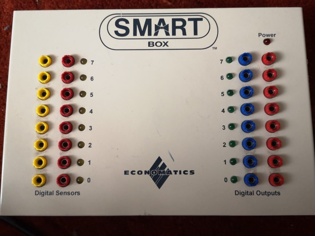
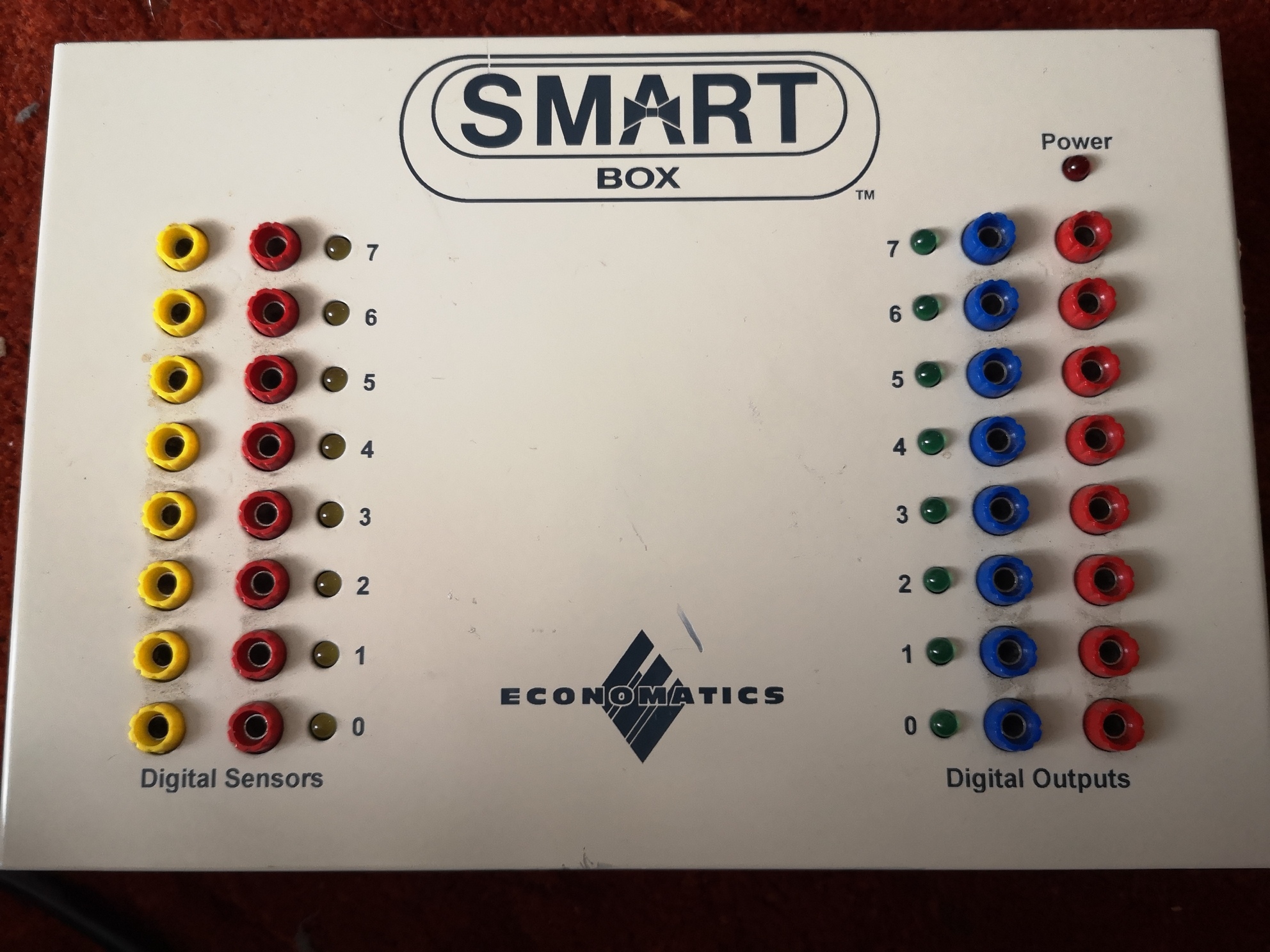
A little while ago, I bought myself a Economatics Smart Box (SB-04). My intention is to reverse engineer the serial protocol so that I can use it from a modern (Linux, but the information will be useful to others) computer. These boxes were common in schools in the UK through the 90s (and possibly before). Older variants worked with the BBC Micro. This is what they look like if anyone has forgotten or hasn’t seen one before :
A couple of minor issues so far – Number 1 – This specific model (the SB-04) doesn’t have mains in like some of the older versions, it has 12v AC in – don’t know about you, but I’ve hardly seen any AC-AC PSUs in years.
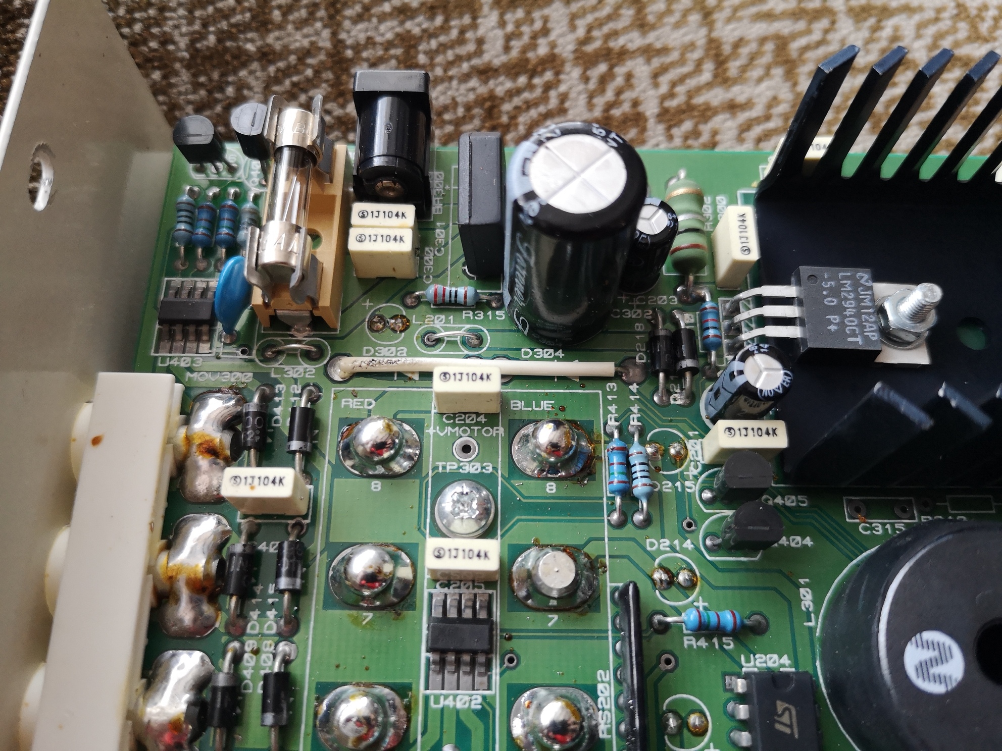
I’m aware that often you can just use a DC PSU of the same voltage with such equipment because the first thing that happens on the circuit board is that the supply is rectified and smoothed… using a DC supply just means that the supply is always going through two of the diodes and the capacitor remains permanently charged. As long as you’re within the diode ratings and the resultant voltage is close enough, there isn’t an issue. My thought was to check the circuit and see if there was any obvious reason why this wouldn’t work, which is where we get to issue Number 2…
Anti-tamper screws. I managed to get these out using a tiny socket and pushing down hard.
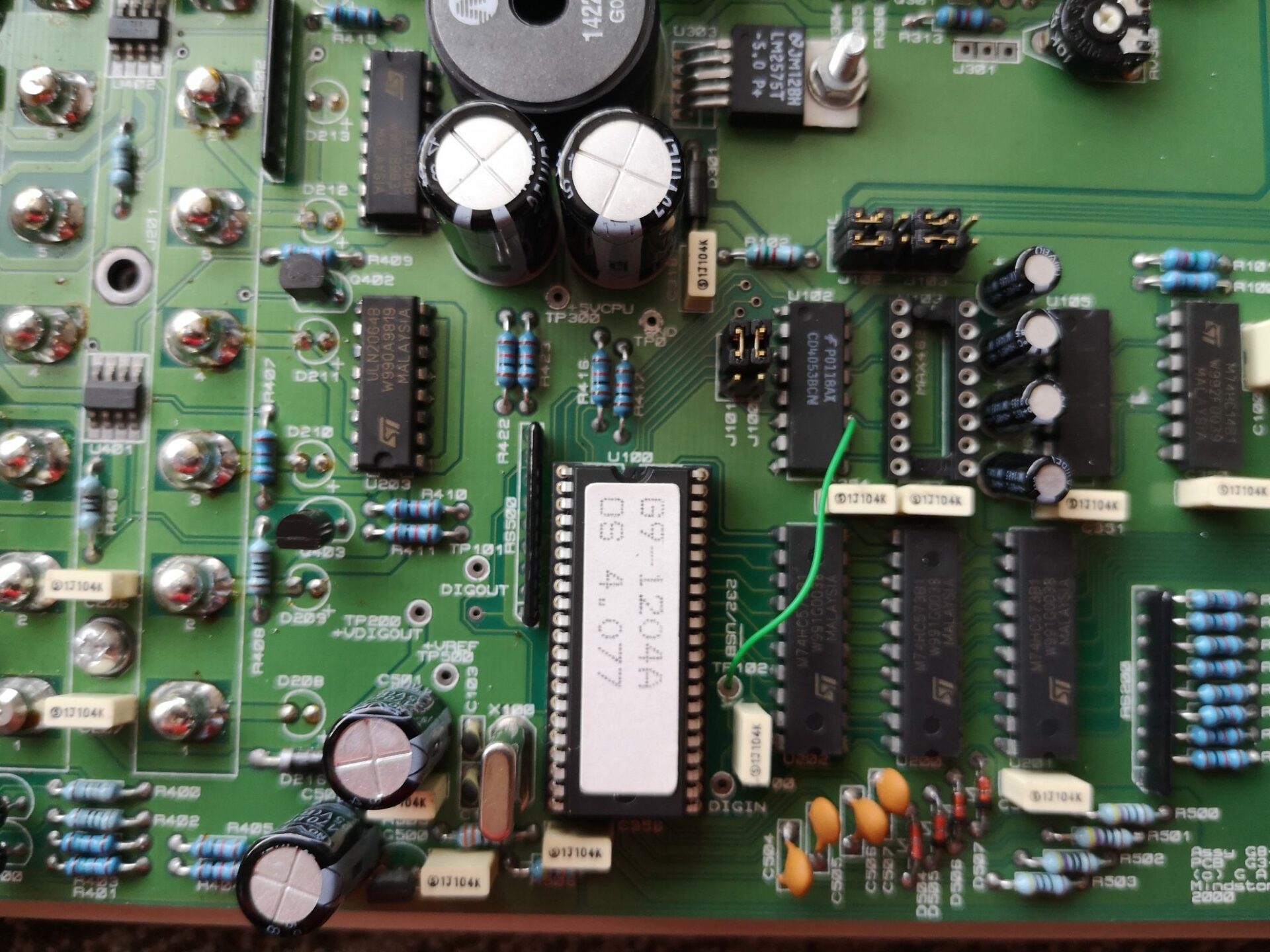
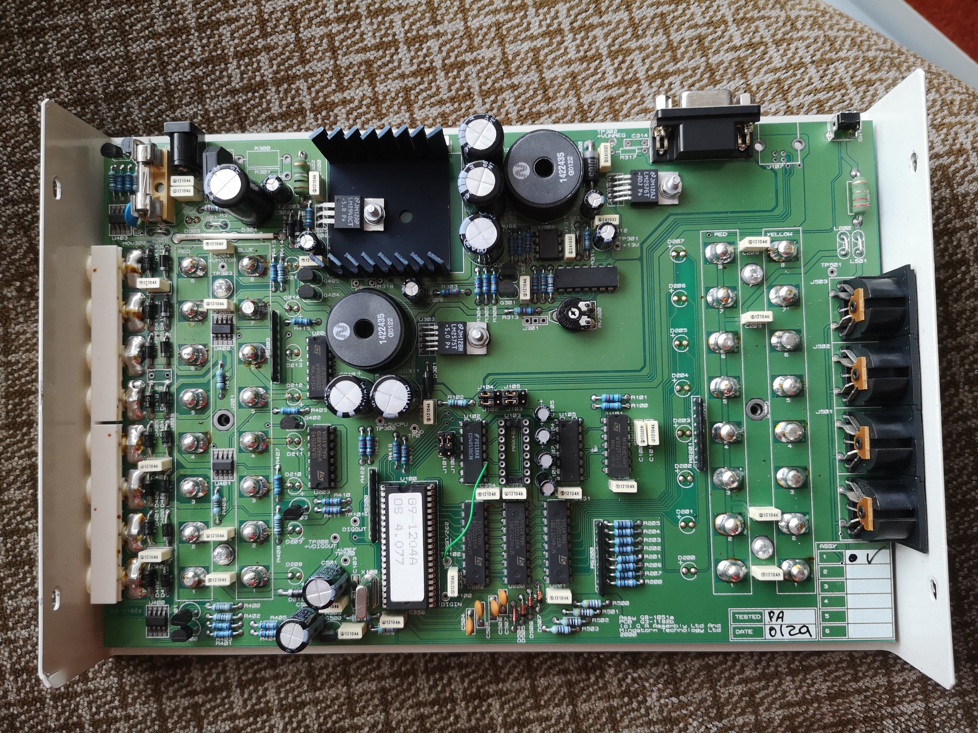
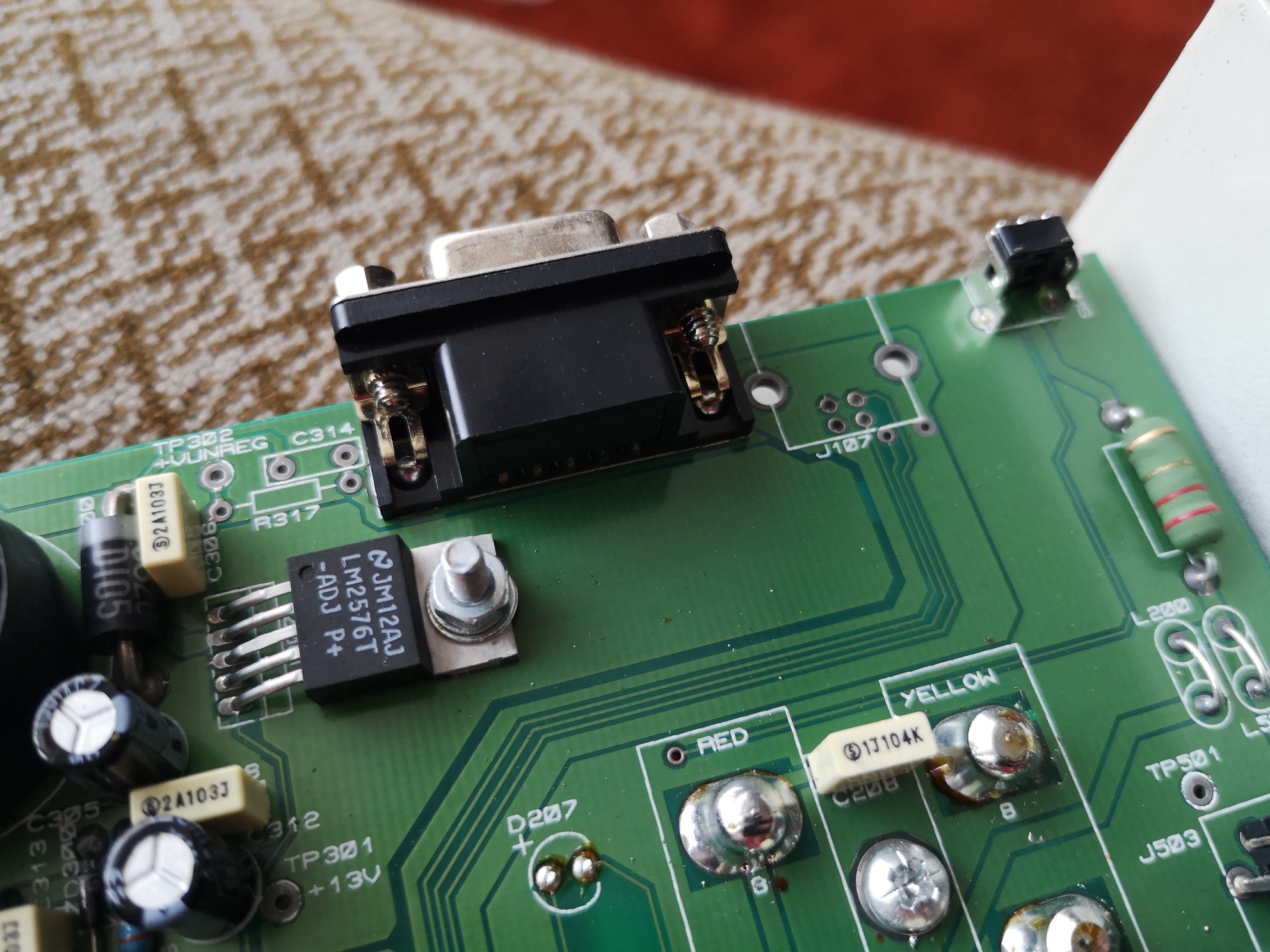
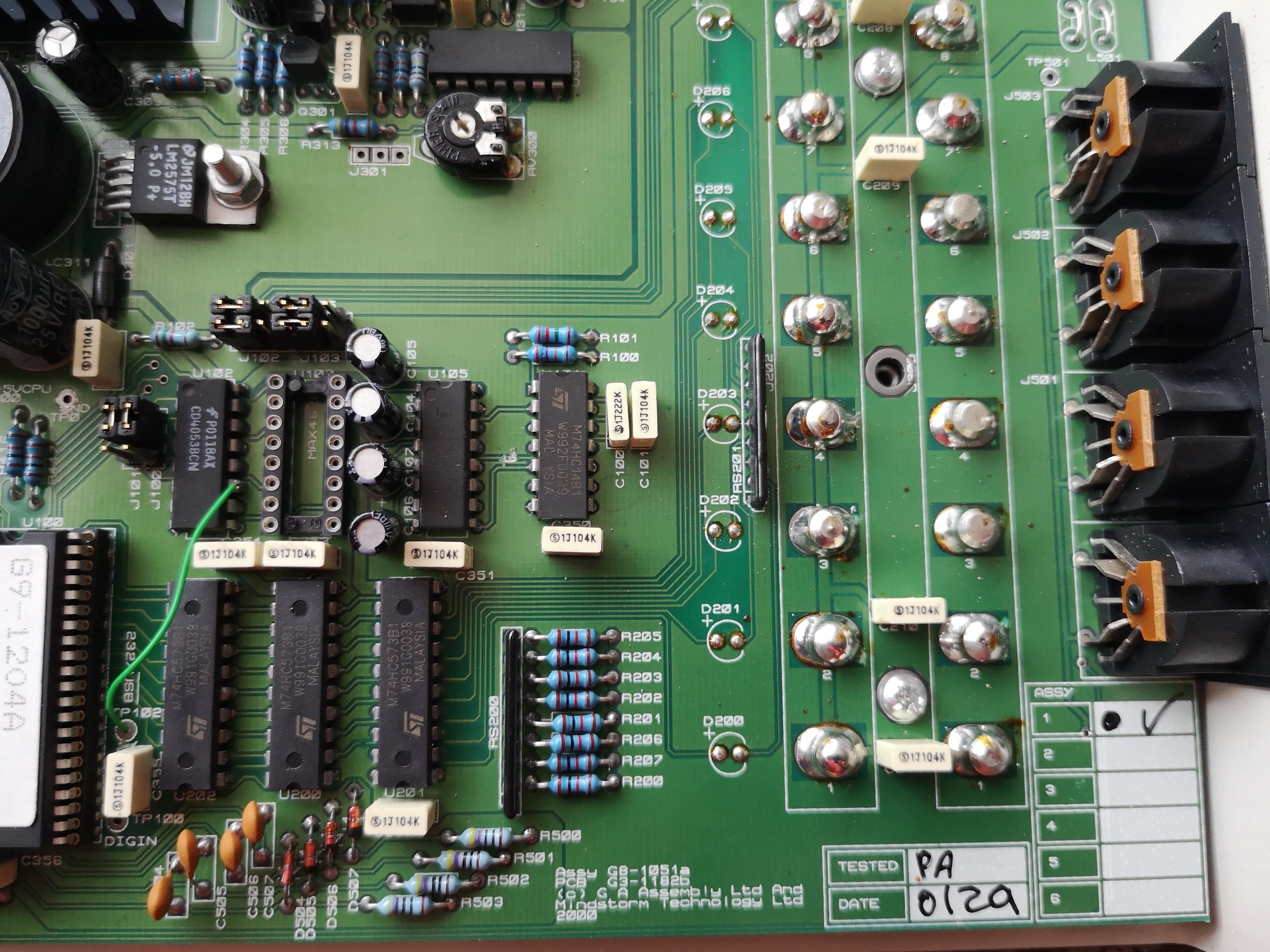
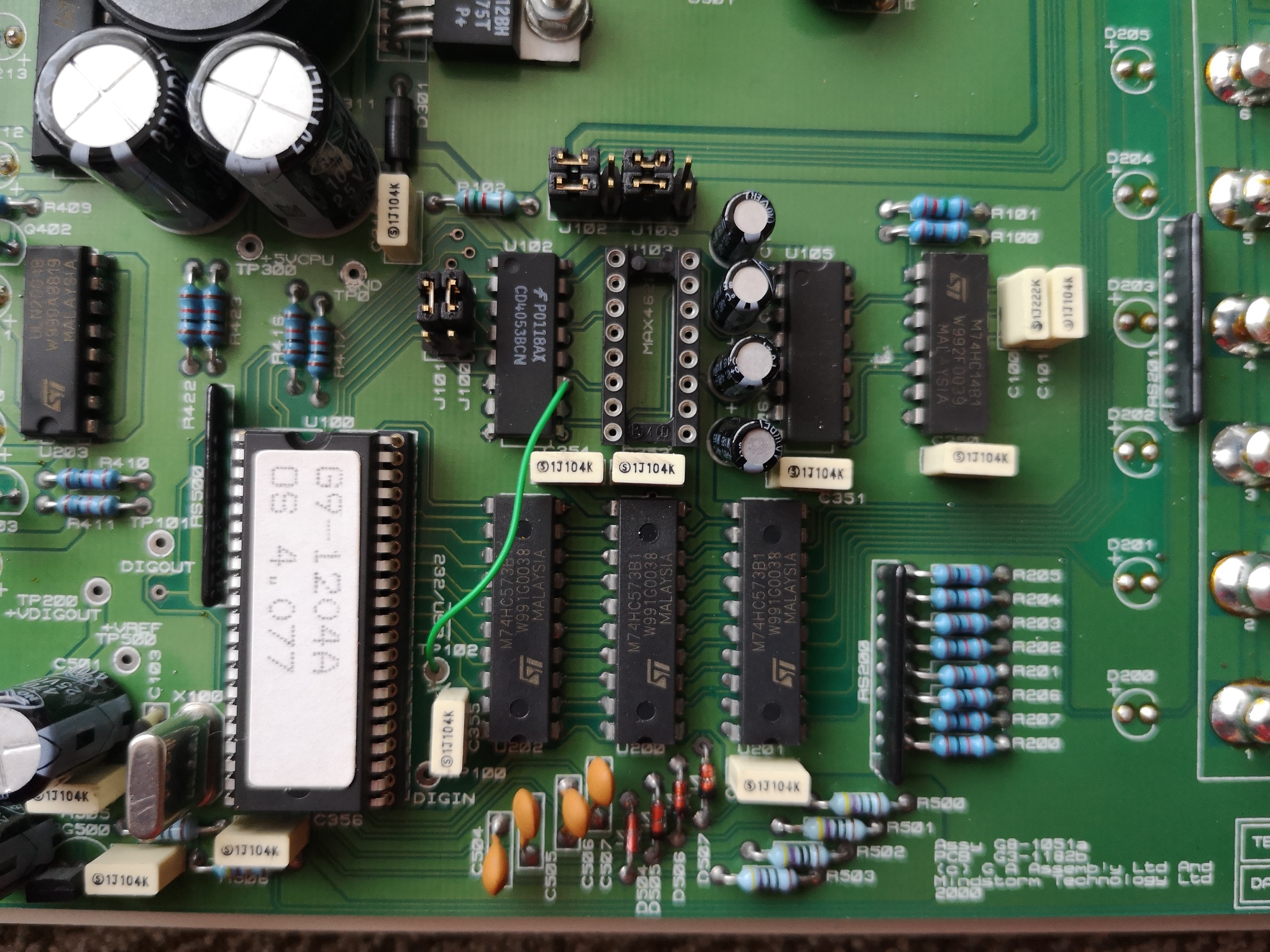
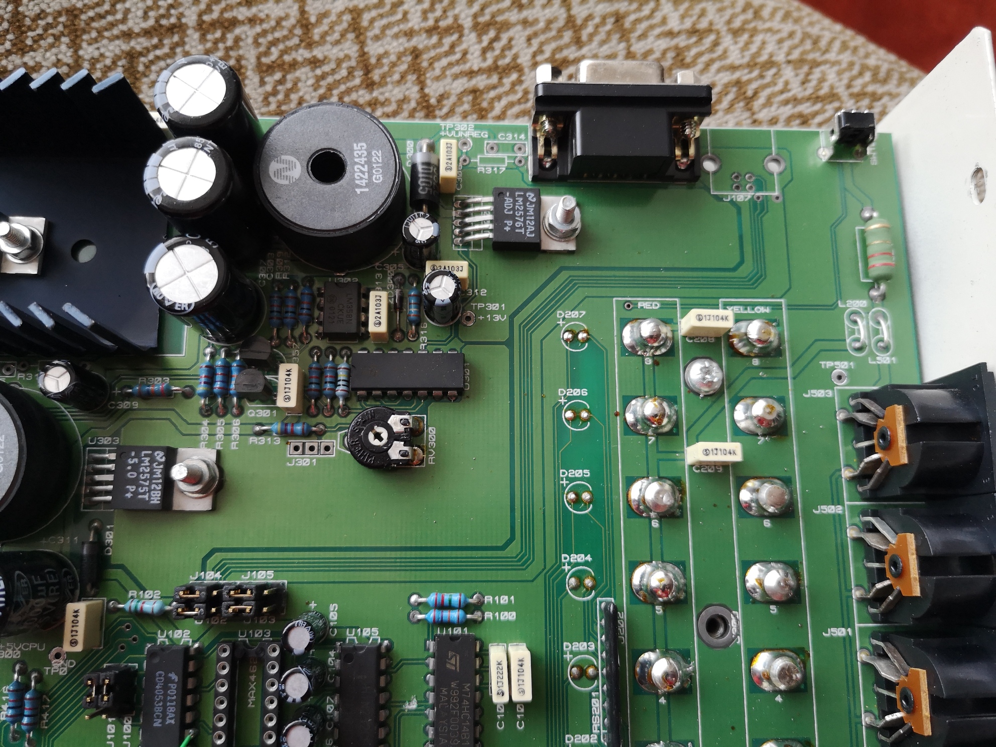
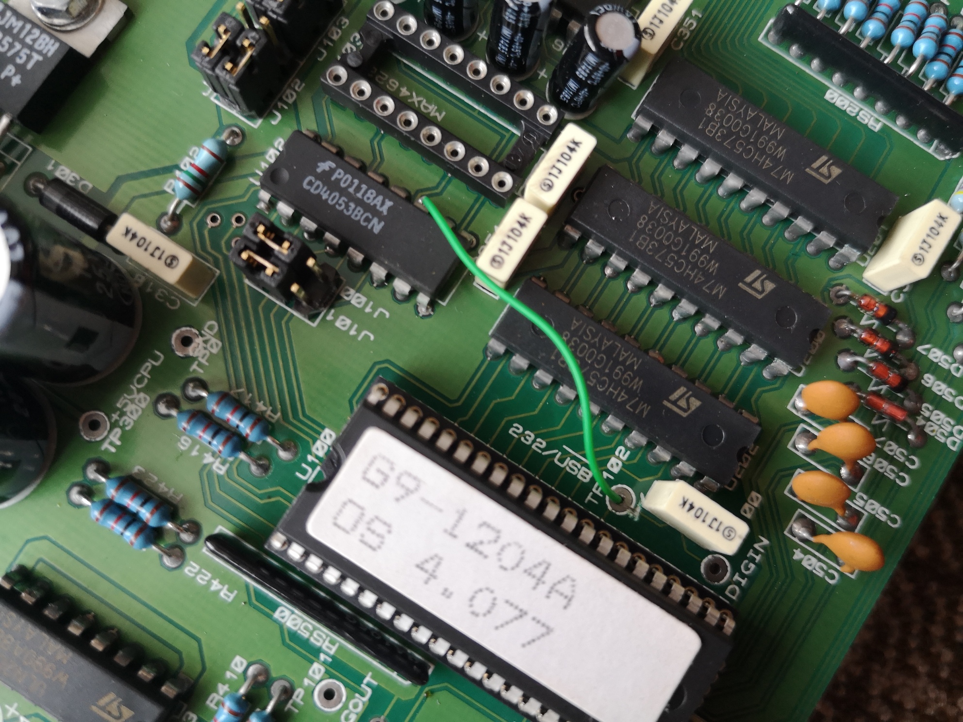
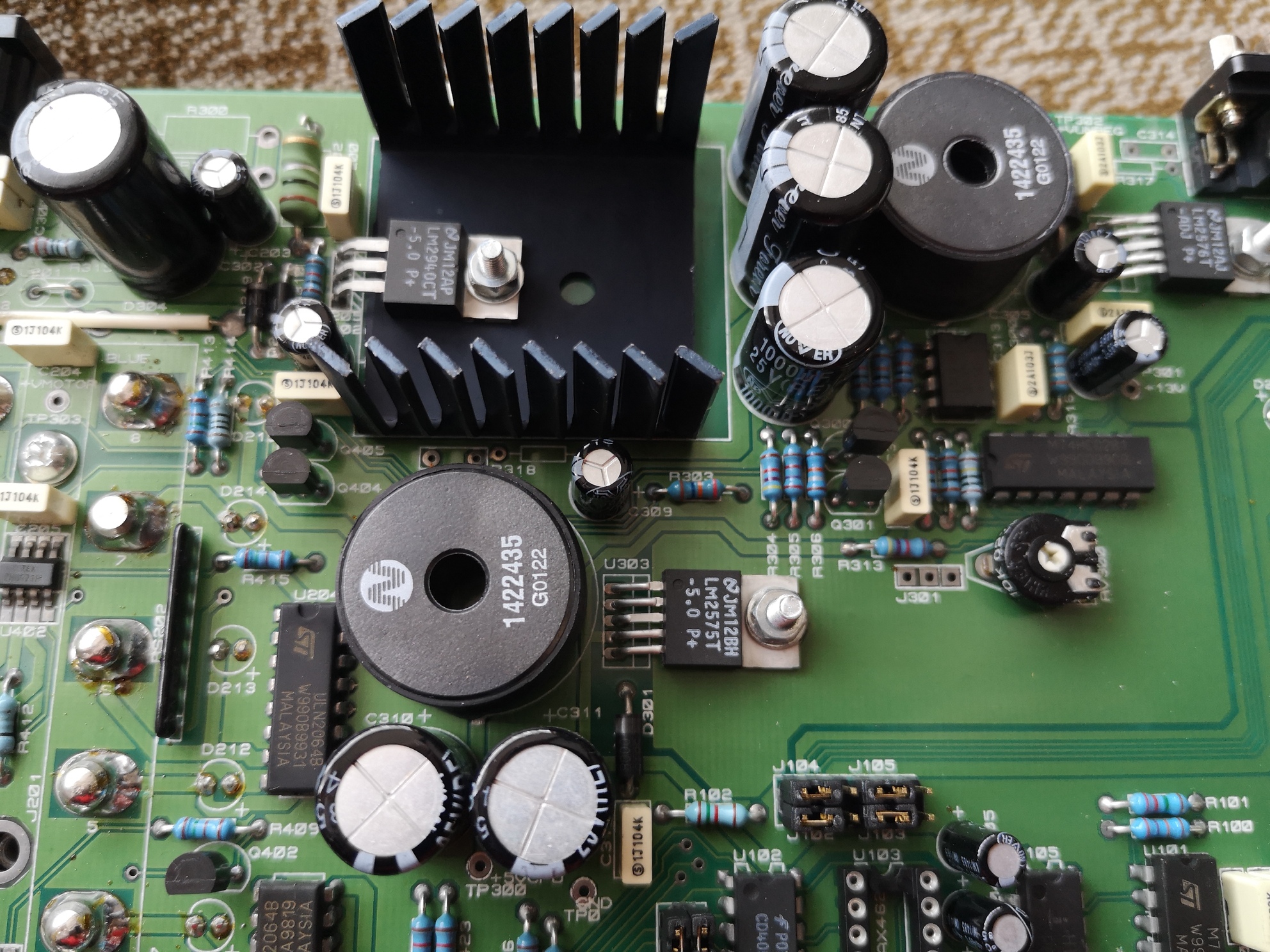
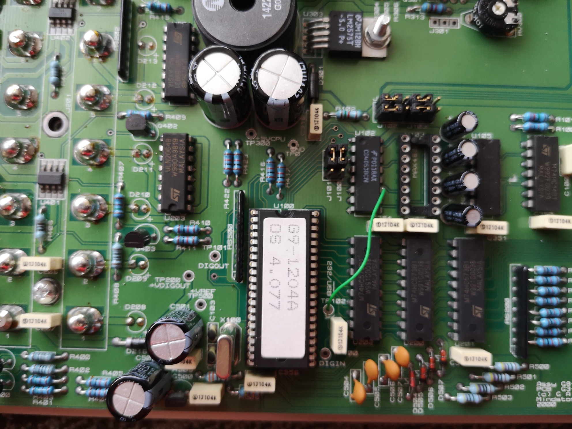
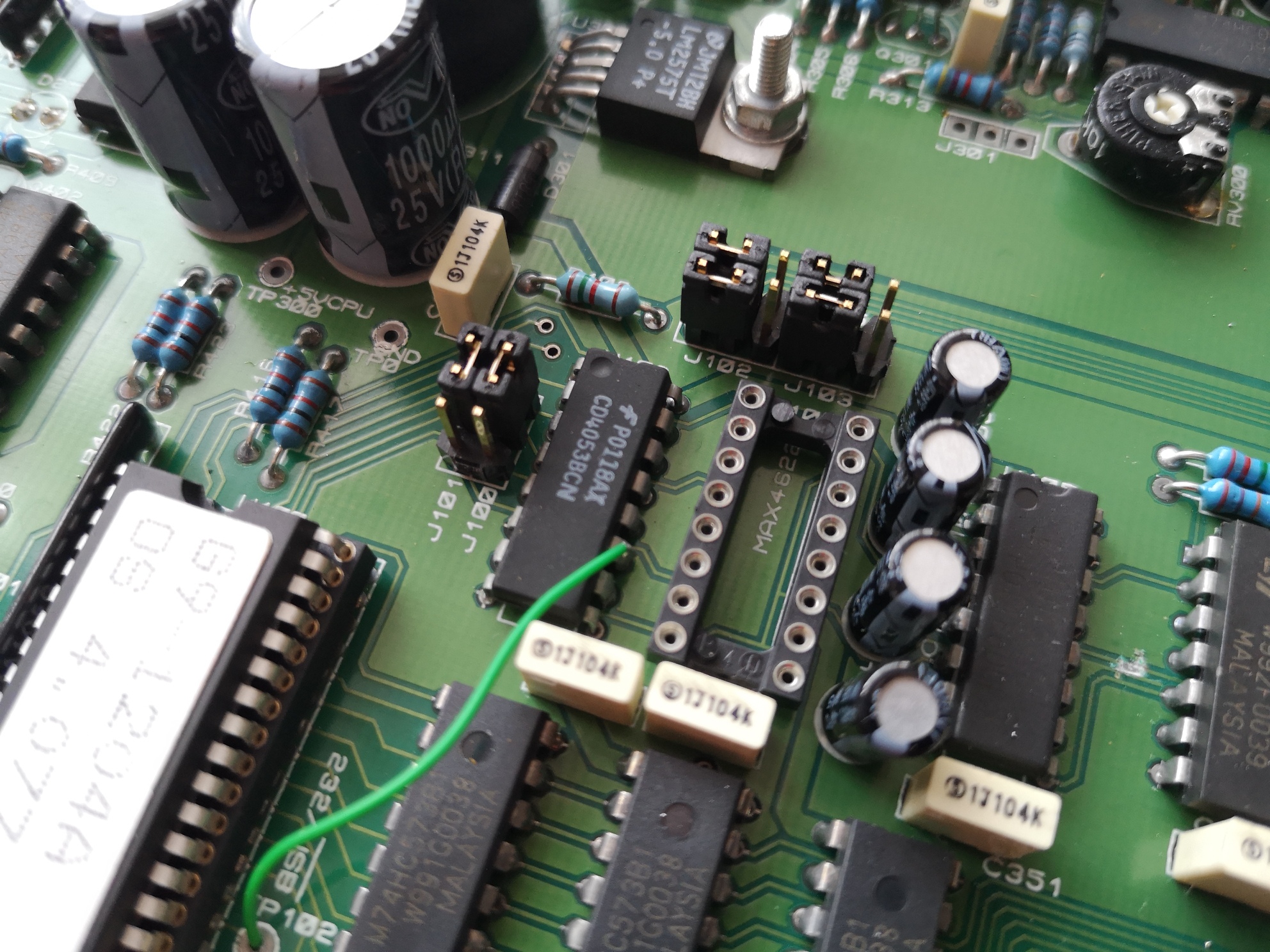
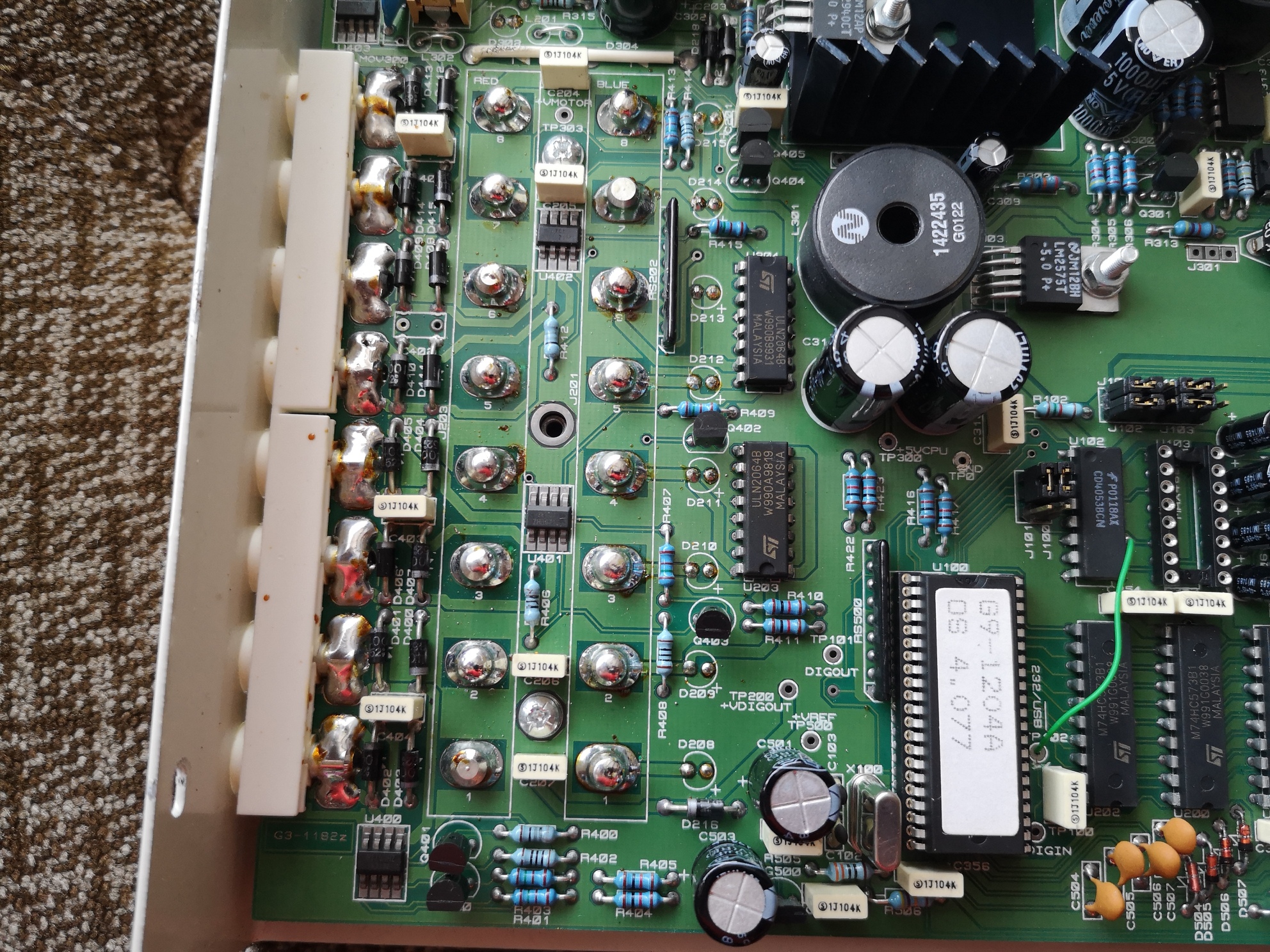
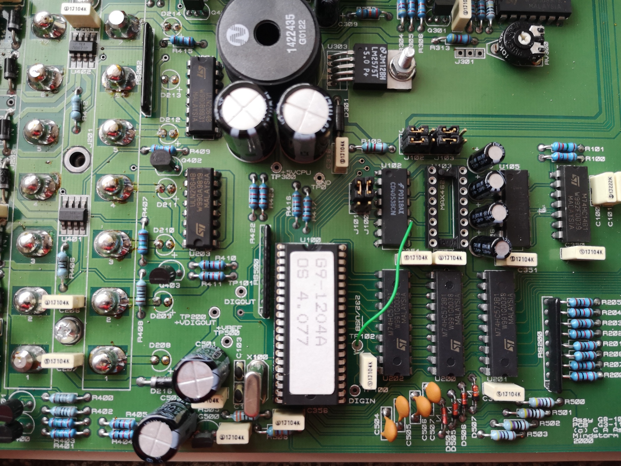
Lovely looking PCB inside designed by “G A Assembly Ltd” and “Mindstorm” (I wonder if there is any connection to the Lego Mindstorm?). Note one bodge wire, a socketed chip with the firmware version (with an unusual pitch), a missing MAX4622 chip (single pole double throw fast acting switch https://www.maximintegrated.com/en/prod … X4622.html) and space for a USB B socket. The digital outputs are buffered with ULN2064b chips (these are darlington pair arrays).
Anyway, I’ve got distracted.
First point – there is no obvious rectifier, the PSU portion of the circuit is complex and includes two large inductors by the look of it. I’ll have to do a bit more digging and look up what some of the components are.
Second most important point – does anybody have a photo of the USB version of this board – I’d be interested in adding USB if I can. Current theory – the bodge wire is hardwiring my board to Serial and saving the need for the MAX4622 chip for switching between USB and RS232. There are a bank of jumpers that look interested and are next to the USB lines. I’m also wondering is the firmware the same in the USB and Serial variants?
Photos of the top side of the PCB (actually the bottom as it sits on the desk) for interest.
I think the main chip might be some kind of 6502 based MCU or similar – I can’t find a good datasheet online that exactly matches. It has a reduced pin pitch, 42 pins and it looks like the Crystal is connected to pins 19 and 20.
A 6502 based MCU would make sense given that the company made BBC Micro peripherals.
Older versions of the board are basically an embedded 6502 computer with RAM, ROM, an ADC and a VIA. My newer version is based on a Mitsubishi microcontroller, the M37536E8SP.
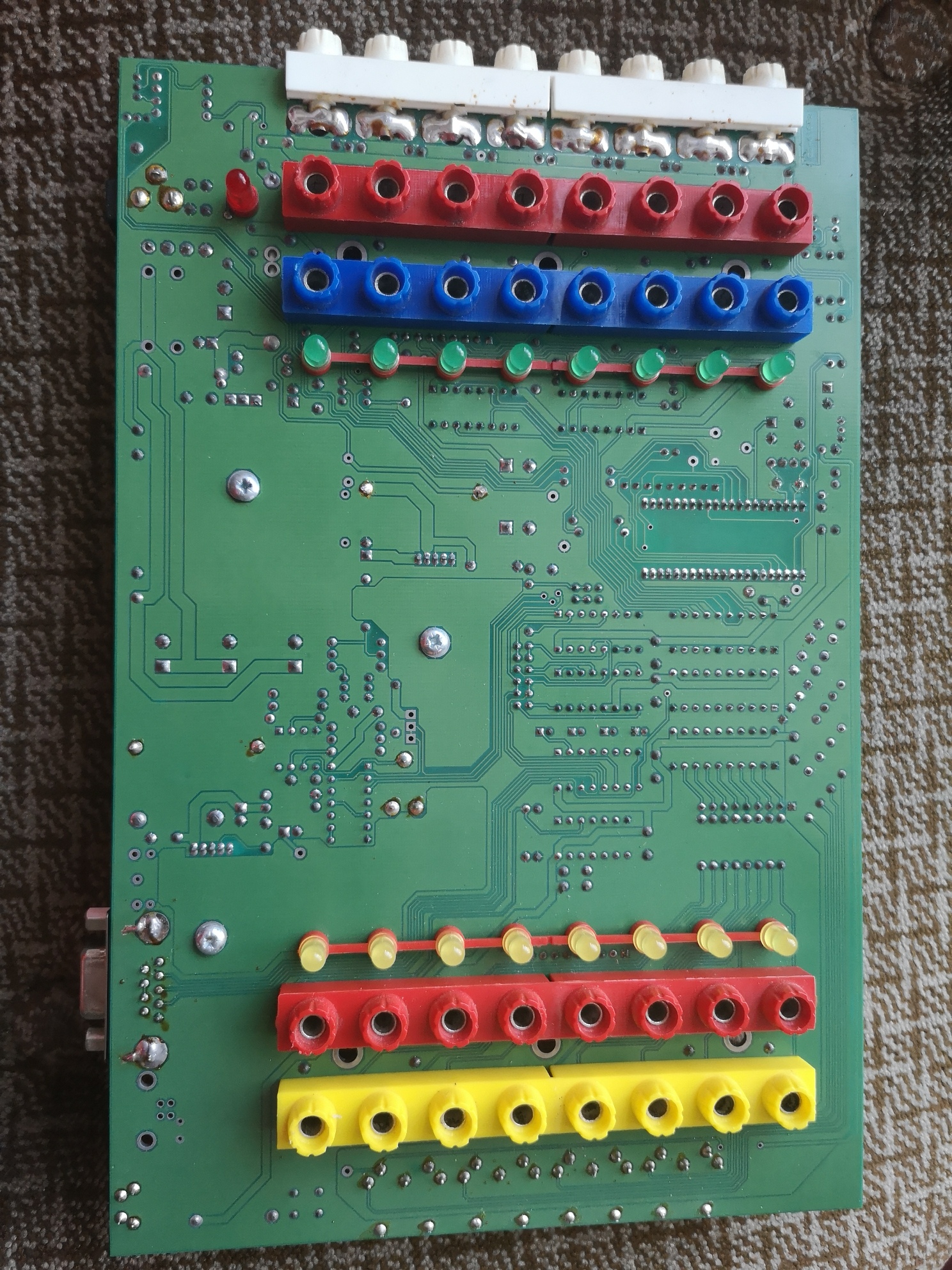
I’ve taken the board completely out of the case now. No components on the reverse, but useful for tracking traces. I’ve also noticed that there is a cut trace next to the test point that the bodge wire is attached to (separating it from a capacitor that looks like it is attached to a power rail judging by the track width – they must have accidentally tied it high).
Underside of the PCB :
Thoughts welcome, photos of the USB variant would be gratefully received!
Update – Some progress. I have digital write working from Python. I was lucky enough to find this page, which includes a download of sample code for controlling the Smart Box from VB6. Helpfully, this includes a number of the serial commands for making the box do various things. I’ve been able to extract the commands for the core functionality.