PowerComputing PowerTower Pro Project
Note – This Project is ongoing, and so this page will be updated in a very untimely manner as I undertake and document additional work on my PowerTower Pro.
Background
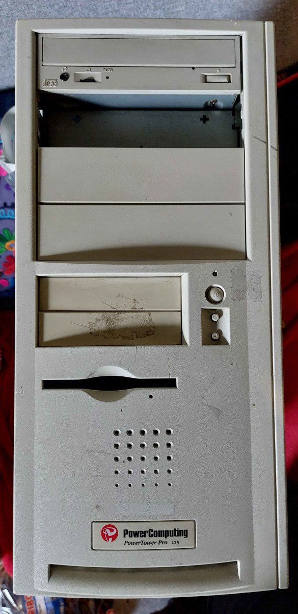
For a long time I have wanted a Macintosh Clone, basically because they came in more rugged cases and the power supplies should be easier to replace long term (which isn’t as true as I thought it was). Unfortunately, prices went up significantly and I haven’t been able to justify buying one, but recently I saw a PowerComputing PowerTower Pro 225 for sale “not working” on eBay. It was pretty rough with lots of missing parts and some dents and scrapes, but I picked it up as a project.
Condition on Arrival
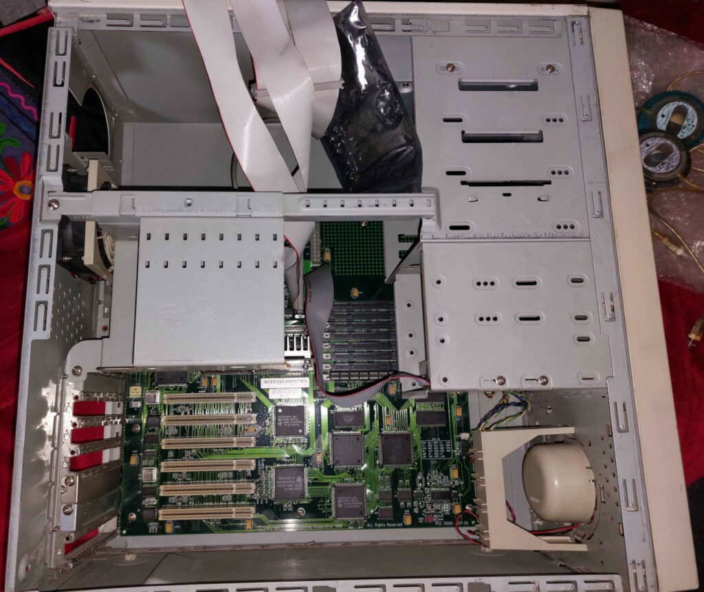
- The original CPU is missing and a 9600/
200233 CPU has been fitted. The original part would have been a 225MHz PowerComputing card. - Sadly the Level 2 Cache is missing – this is really unfortunate as the original part will have been a 1MB module, which are hard to get hold of. I don’t anticipate I’ll ever be able to replace this.
- The 80mm rear case fan is failing.
- The 80mm CPU fan is missing.
- The CD Drive does not look like the original part, and I suspect is a slower replacement. I haven’t tested whether it works yet.
- No hard disk fitted.
- One 5.25″ bay plastic cover is missing.
- The light pipe for the power button is broken.
- No video card (stock it would have been supplied with a 2MB ATi Mach64 / Rage of some description, a 4MB ixMicro TwinTurbo, or an 8MB ixMicro TwinTurbo. I’m not sure if all three options were available in this specific tier machine.
- The PSU is missing.
- There is a single 64MB RAM module fitted. Given the computer interleaves RAM, it really should really have a matched pair, I anticipate it probably originally shipped with a pair of 16MB modules. This is more frustrating that I realised because I seem to have run out of my stockpile of 5v 168 pin RAM modules. I might have to downgrade another computer, which is always a shame.
- A number of screws and PCI slot covers are missing (and the ones that are there don’t match).
- The case is a bit beat up, as well as being dirty and the paint scratched, there are a few dents and panels don’t quite align properly.
- The logic board has been re-capped. They don’t appear to have cause any actual damage, but some rework might be good to tidy things up a little.
Given what is missing, I suspect this was a tricked out machine at some point – I suspect it had a number of PCI cards, much more RAM (otherwise there would be matched pairs and the original factory modules would still be there) and I suspect it had a processor upgrade.
The seller stated that they had tried powering it on and it did not chime. On arrival I sprayed contact cleaner in all the slots and undertook a general inspection.
The Plan – Subject to Change
Other than actually debugging and repairing, the following are what I plan to do with this machine to set it up as a usable and useful machine.
Short Term
- Find and fit a suitable PowerSupply. – Done
- Fit a period video card, or one that represents a small upgrade. I’ll either fit an ixMicro TwinTurbo or ix3D, or alternatively I might fit a Radius ThunderColor. – Done
- Install a PCI SATA card. SCSI hard disks are expensive, this lets me use a SATA DOM or similar instead. – Done
- Replace the loud and missing fans with quiet modern fans. – Mostly Done
- Add a second optical drive, probably SATA, to hide the missing bay cover. – Partially Done (Waiting on a beige one)
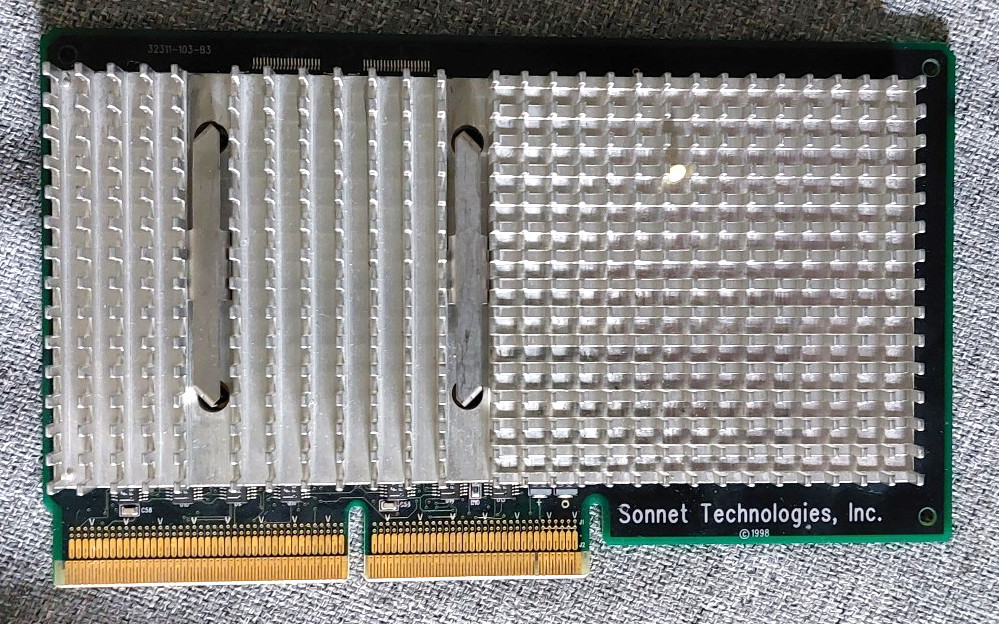
- Fit a G3 upgrade card, probably something around 300MHz. I have a 300MHz green (i.e. not purple) Sonnet upgrade that might suit it. – Done
- Knock some dents out and straighten the case. – Done
- Clean the case. – Done
Long Term
- Repaint the metalwork to solve the battered look.
- Work out how to repair the deep scratches in the front plastics.
- Clean up some residual flux from a previous owner’s recap and visually inspect their work just in case.
- Clean up the floppy drive internals.
- Fix the Power LED. – Done
- I may put a DigiDesign AudioMedia III card in the PowerTower because I believe it was originally the property of a company that specialised in Digital Audio Recording.
Progress
Getting it Booting
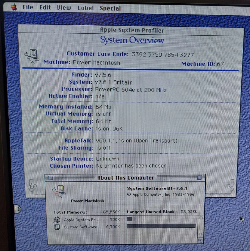
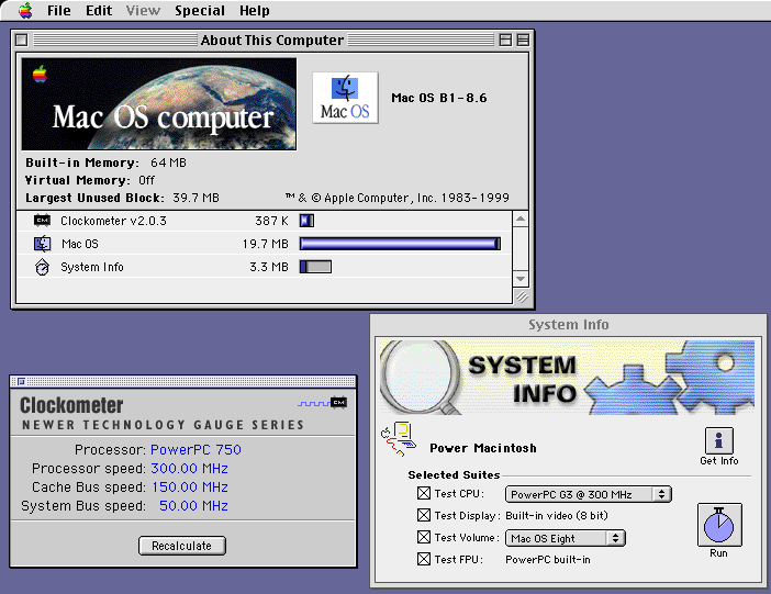
As I’d been told that it didn’t chime, but the CPU did warm up, I decided to try booting the absolute minimum. I couldn’t find a proper ATX power supply, so given I didn’t have any disks and only one RAM stick and no video card, I used my picoATX and a 5A 12V power supply – this is only 60W, but given the 233MHz 604e (System 7.6.1 reports it as a 200MHz CPU, but the part number and Clockometer agree that it is a 233MHz CPU – this is nice because it is the fastest Apple 604e, and a smidge faster than the stock CPU) fitted would only need less than 10W, I figured the remaining 50W or so was plenty for the chipset and fan.
Pressing the power button, the fan came to life, the floppy drive clicked and the CPU and things on the logic board warmed up without getting excessively hot. I powered it off and poked a non-bootable floppy disk in the drive to see what it would do… it tried to read the disk and then ejected it. This is extremely good news. It means that the computer is executing code from ROM and trying to find an OS. I powered down again and plugged in my stereo amplifier and speakers.
Yay! Seems that it does chime, just not through the internal speaker.
I grabbed a VillageTronic MPDD+ PCI video card (because I suspect it probably doesn’t use much electrical power) and popped it in the bottom most PCI slot. Plugged in a keyboard, mouse and VGA monitor and powered the computer on…
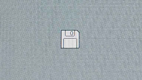
Promising… I found my ZuluSCSI Pico and plugged it into the external SCSI port and it booted right up. I didn’t hang around long, I just booted and checked System Profiler (I wasn’t certain what speed the CPU was, or how much RAM was installed, so now I know it is a 200MHz 604e (update – I thought I did, but it is reporting incorrectly based on the multiplier and it is assuming a 40MHz bus, the CPU is actually running at 233MHz on a 46MHz bus) and 64MB). Given I didn’t have a proper power supply installed, I shut it back down.
Removing Dents and Straightening the Chassis
There were two dents from point impacts in the side panel. I removed these by placing the side panel on top of a piece of wood and then hitting the inside (high spots) with a rubber mallet. This worked surprisingly well, the case is made from an extremely ductile grade of steel.
The case stands on four large feet, someone had managed to bend the case between the front and back feet so that there was an arch in the bottom of the case. I straightened this by hand, again, it bent back surprisingly easily.
Some of the side panel latches were bent out of shape. I adjusted these back closer to their original shape using a pair of small pliers. Don’t over twist them as it feels like they would break if worked too much.
I also used the mallet to adjust the overall shape of the case a little as it wasn’t quite square. If you do similar, obviously take care, perhaps remove any hard disks first.
The Next Day – Power Supplies, Fans and Sound
After getting my hands on a cheap next day delivery power supply I found that the power socket on the back wasn’t low enough to fit. I was already worrying about the fan position, as like most modern power supplies it has a large 120mm fan in the “top” as orientated in this case.
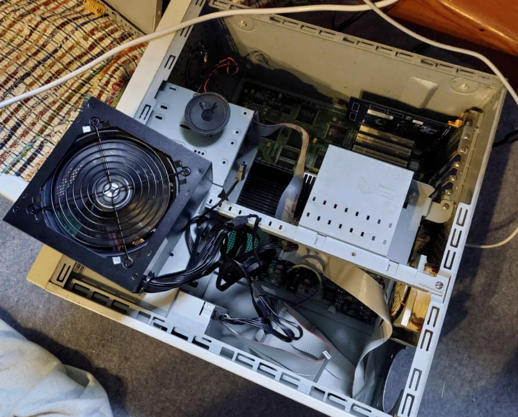
For now I just used the power supply with it placed on top of the case, with the case on its side for a bit more testing. While I was at it, I replaced the rear exhaust 80mm case fan with an 80mm Noctua fan. It fits, and the provided 3 pin cable matches the logic board fan connector. The only issue is that the existing fan guard doesn’t clip into place due to the mating material being a little thicker on the Noctua. This means that it is a friction fit instead of being held fast by the clips. This will do for now, but I might come back to it later. I don’t want to glue it because I want to be able to replace the fan again in the future.
I had looked at the internal speaker and cleaned the contacts where it connected to the logic board, but it still wasn’t chiming. After removing the speaker and holding it to my ear, I could hear that it clicked when the computer powered on. Before doing anything more complicated or costly, I thought I’d check the basics…
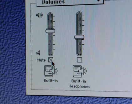
So… it turns out that the PRAM on this computer defaults to the built in sound being muted (I’ve had the battery out). Either that or it is falsely detecting that something is plugged into the external port (I’ve since investigated and I believe the issue is with the rear port). I un-muted the Built-in sound and…
Bingo, turns out sound does work. Mostly.
I left the computer running for about half an hour – it is so quiet I almost can’t hear it, which is bliss compared to most of my vintage machines. I’ve decided that I want to keep it like this and so have ordered an extra quiet 80mm fan for where one is missing for the CPU, and another to fit into the power supply I will end up using.
I noticed that the computer threw an error and crashed while sat idle. I don’t know why yet, but my first suspicion is that perhaps someone has removed the heatsink from the CPU and broke the thermal paste bond between the CPU and heatsink. Hopefully it isn’t anything too difficult to fix – I’ll come back to it and do some load testing with TechTool.
Onto finding an appropriate power supply…
The requirements for a power supply for the PowerTower Pro are as follows as far as I can see :
- The fan must be in the rear face of the power supply, and flush.
- There must be no power switch or LED sticking out (looking at you HP).
- The IEC power connection must be low down, and not vertically orientated.
- The internal power connectors must be compatible with 20 pin ATX and preferably have several “Molex” 4 pin 12v/5v connectors for powering drives.
- The power supply must provide 3.3v, 5v, 12v and -12v. I haven’t confirmed if -5v is required, but it was present on the stock power supply.
- Macs and clones from this era heavily rely on 5v. This is unlike more recent power supplies which provide more 3.3v, or even 12v for the latest models. Finding something that can provide over 45A for 5v like the original 9600 ~400W power supplies is almost impossible and so some compromises need to be made. See below for an extract from the PowerTower Pro manual. If possible aim to be near or exceed these values, especially the 5v current.
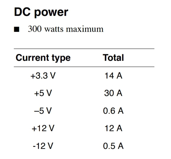
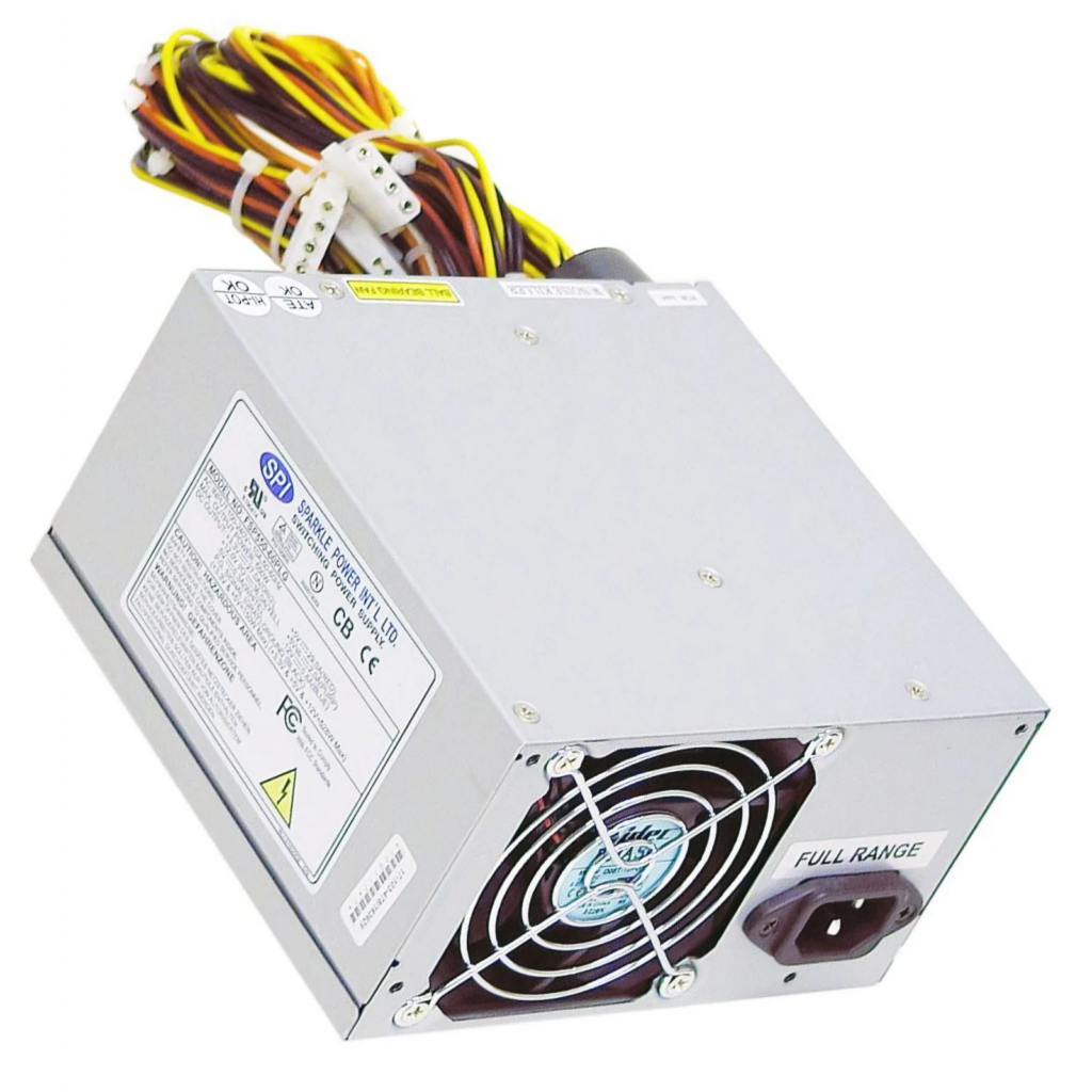
After several hours looking at power supplies on eBay, I decided that I wanted either an FSP300 or FSP350, specifically the PLT variants as these have stronger 5v rails than most power supplies. Additionally, the power connector and fan are in the right location, and I was able to find one for sale for a reasonable price. I ultimately bought an FSP350-60PLT, with a 5v rail capable of providing 32A, but the FSP300-60PLT would also be perfect. The -5v provides a small amount less current, but I doubt this is an issue.
The following shows the ideal arrangement of power socket, fan and no vents on the top surface (the one I bought does have vents in the top, but I’m hoping that there are more vents elsewhere, or that it wont be enough of an issue to matter) :
Fan and a Bit of TLC
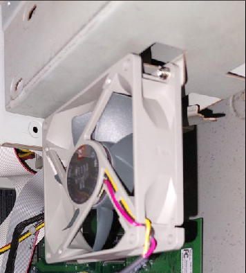
The additional fans I ordered arrived, so I mounted one on the bracket that holds the Processor card in place (and also looks to have space for two hard disks). I don’t know what direction the original fan faced, but I orientated the new one to draw air upwards away from the CPU towards the exhaust fan and PSU. The fan was an 1800 rpm Noctua and was louder than the slower version I used for the rear case fan, so I used the adapter that came with the other fan that I assume is just an inline resistor that reduces the speed of the fan. It is now basically silent again.
I’ll quickly skip over a few things I did because it isn’t very interesting, but I…
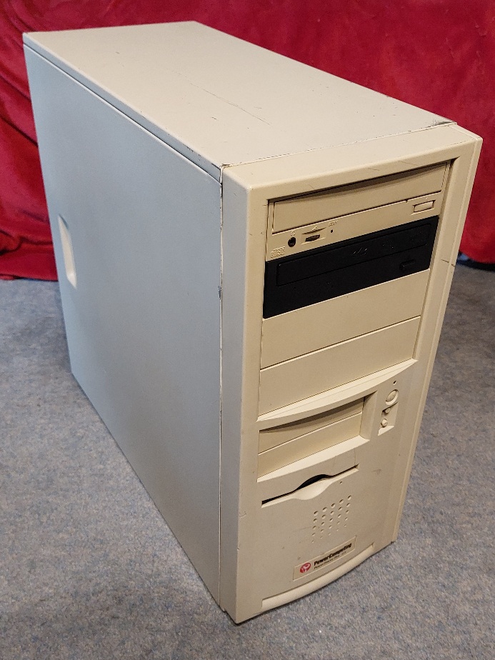
- Cleaned the exterior of the case. I used IPA which was overly aggressive on the paint, so I recommend you use warm soapy water if you are doing the same (Image 1).
- Removed the plastic front (Image 8). There are three latches down the left hand side and one more on the bottom right. Release these and the front should pull off (Image 2).
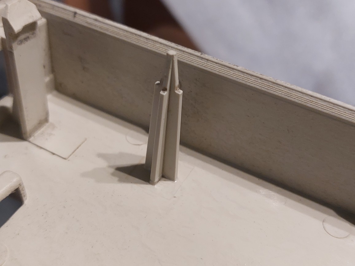
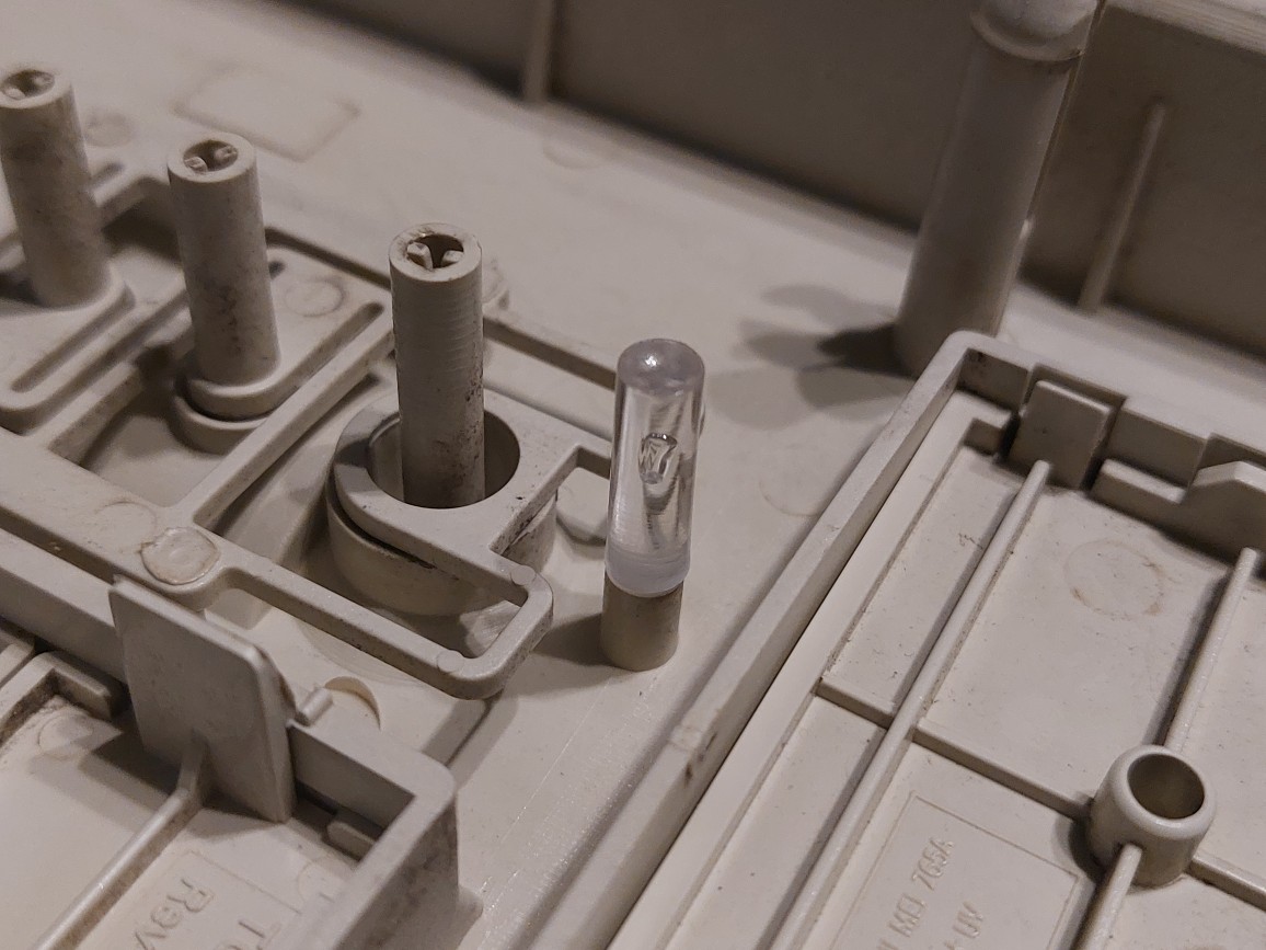
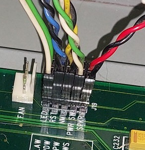
- Glued a broken support back on (Image 3), and glued the power LED light pipe back together (Image 4), it had dropped out the first time I opened the case. I ended up using superglue for both, but a plastic cement or Acetone might be better for the supports. After re-assembling, I actually found that the power LED still didn’t work, but it was just that a previous owner had attached the LED wires back to front, so swapping them over fixed that issue (Image 5) (Image 7).
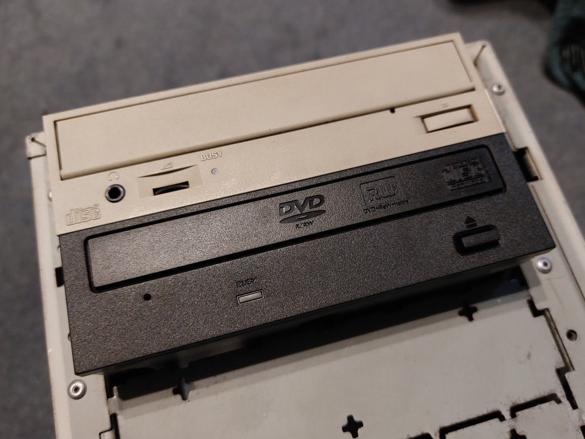
- Fitted a spare, black optical drive to fill the missing opening in the front (Image 6). I had to knock out a metal blank to do this (Image 8), and am unfortunately missing a support rail that should go on the right hand side. A beige drive would look better (Image 1).
- Installed PCI slot covers where they were missing.
- Fitted thumb screws to the rear of the case (Image 9).
Here are some photos of the above.
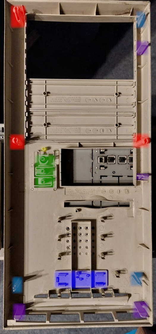
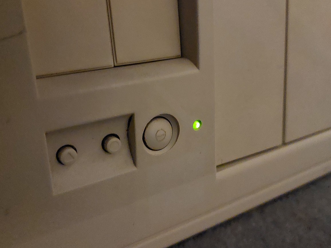
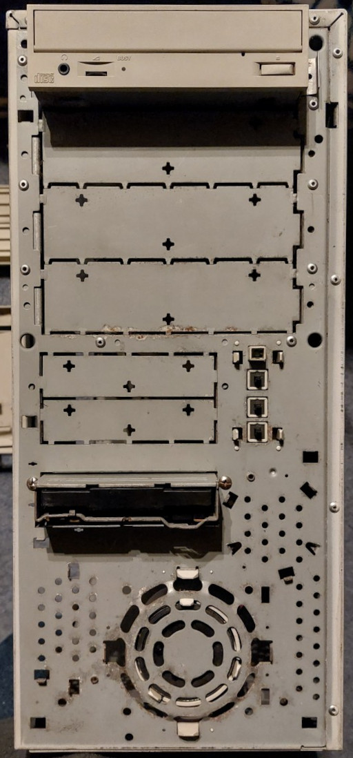
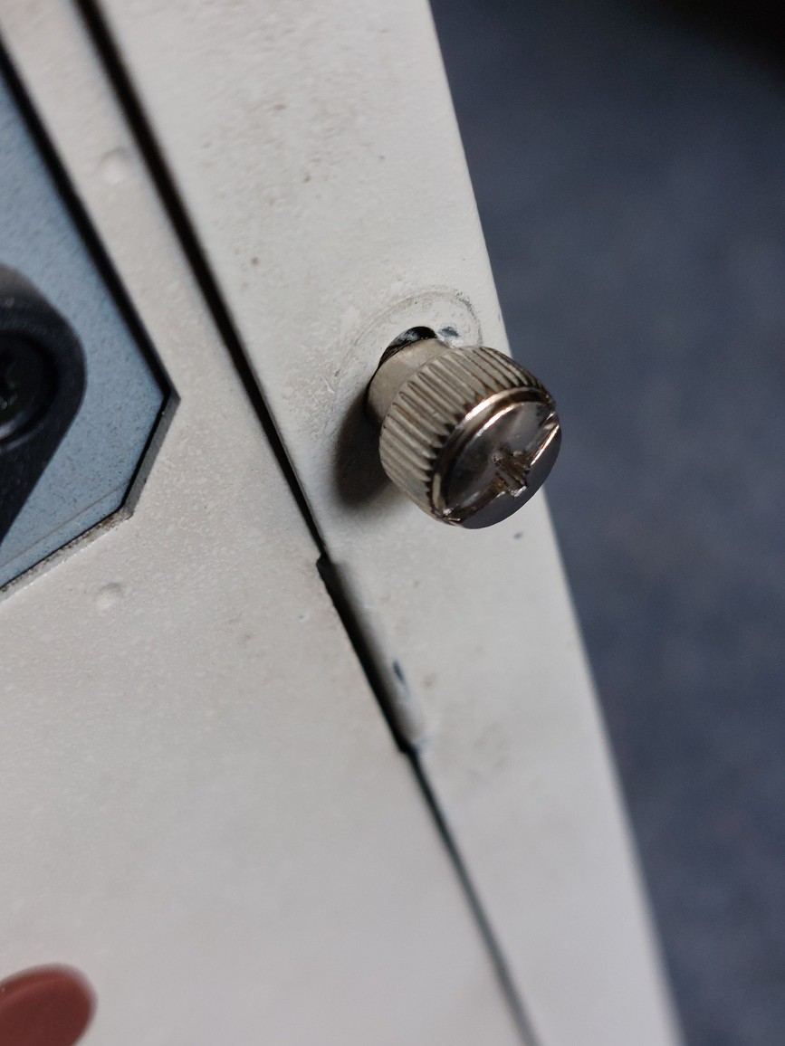
In Image 2 above, red are clips, purple are latches, light blue are supports, dark blue is the removable case badge, green are the power, reset and NMI buttons. Yellow is the LED light tube.
Putting the Power in PowerTower Pro
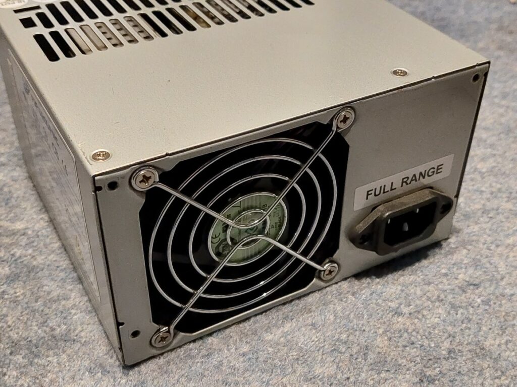
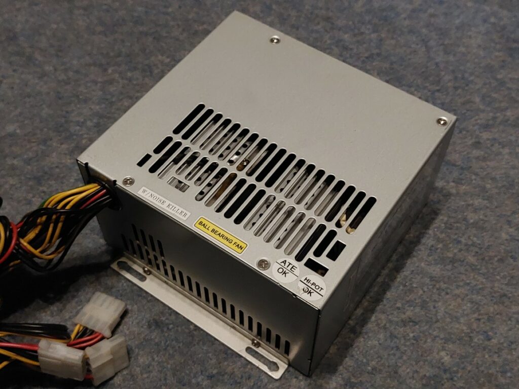
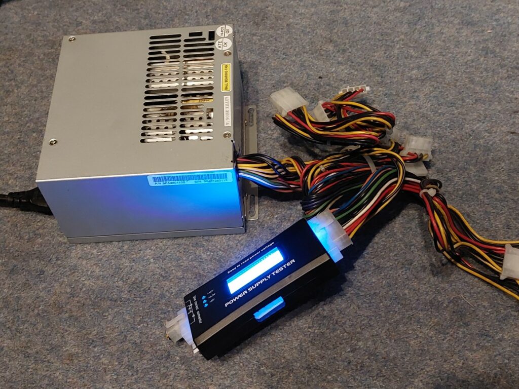
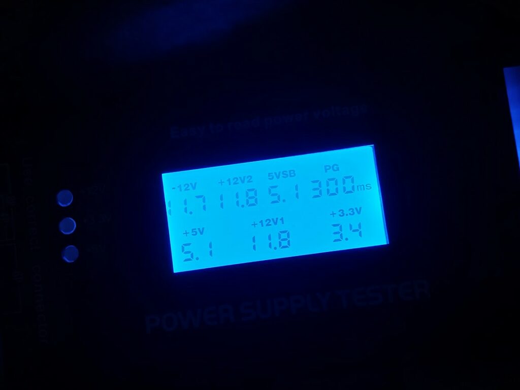
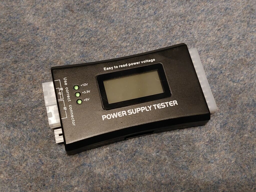
Just in time for the weekend the FSP350-60PLT power supply I ordered arrived. Given it isn’t new, before installing it in the PowerTower, I connected it to a tester I got from Amazon to verify the voltages. It would have been sensible to put an artificial load on the 5v and 12v rails by plugging resistors into a Molex at the same time, but mostly I just wanted to know that the power rails were at sensible voltages and not unstable.
Once satisfied, I installed the power supply in the case. It really has a few too many Molex connectors and was doing a very good impression of the Flying Spaghetti Monster, but I did my best to push them out of the airflow from the CPU and PCI bay.
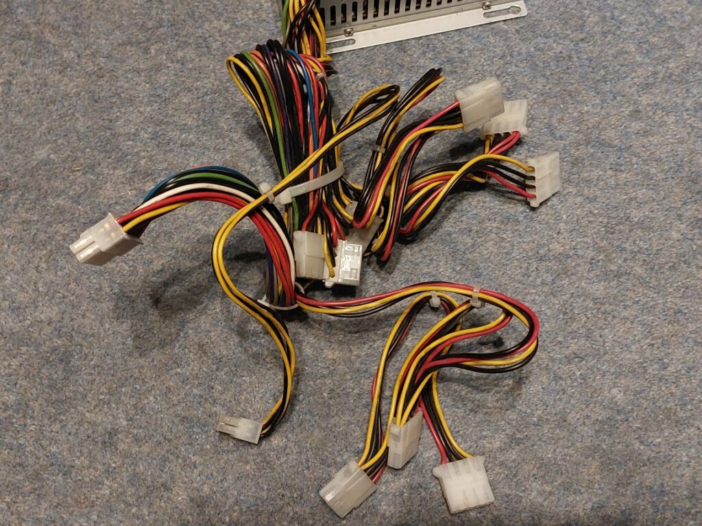
The good news is that the power supply is a perfect fit. The fan is even fairly quiet – I’d say it is about the same volume as an 8600. I’m unsure if to try to reduce the noise with a quiet fan, but I’m reluctant as most of the noise is air noise, meaning a quieter fan would likely only make less noise by moving less air. It makes me uncomfortable when I see people replacing “loud” fans with less powerfull ones designed for lower pressure drops, based on the open air airflow rates. But that is for another day.
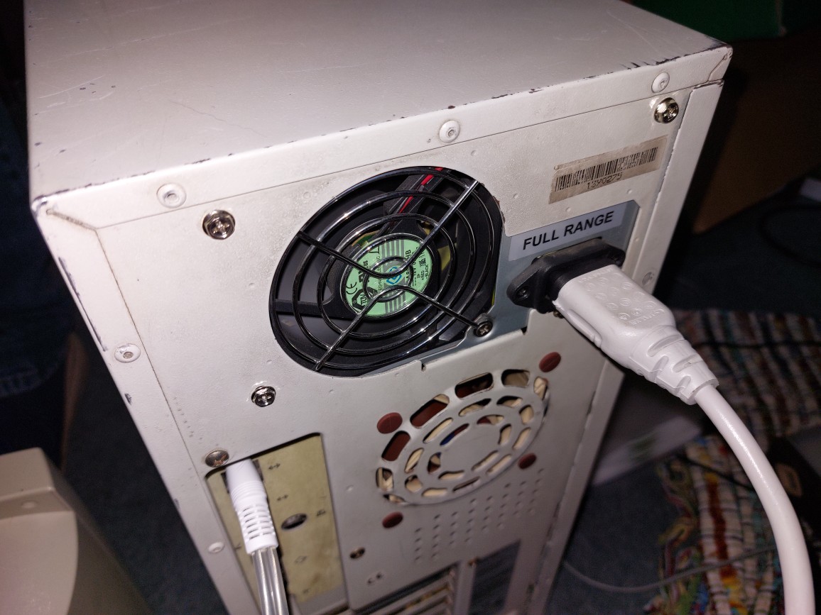
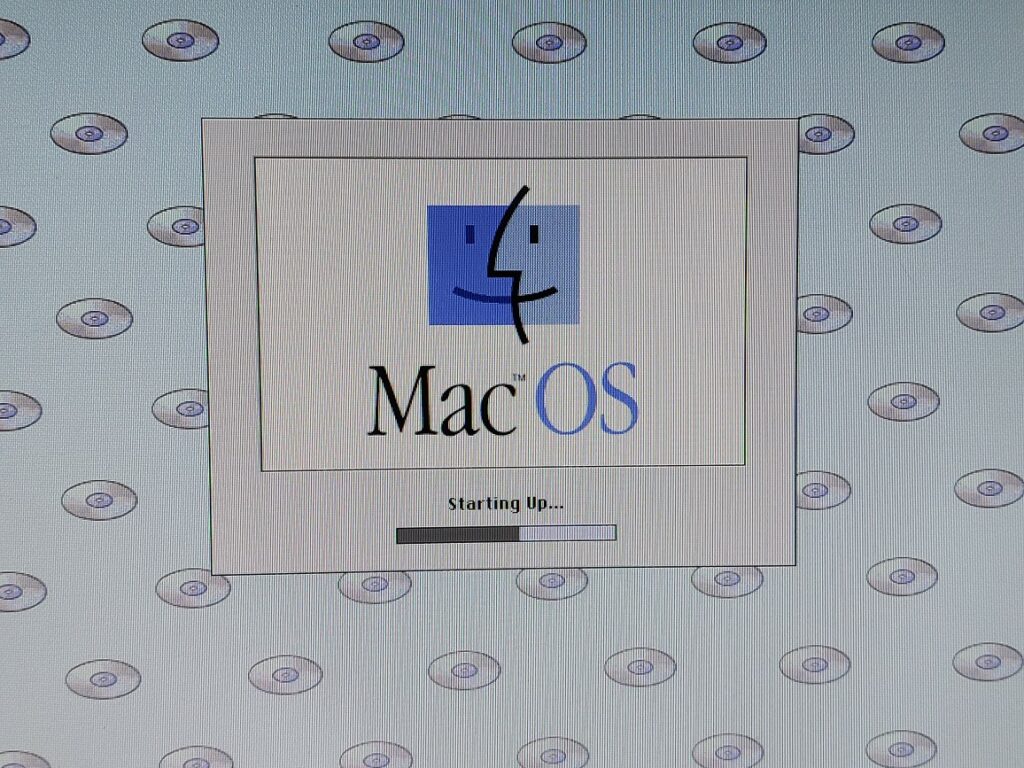
This is the first time I’ve been able to boot the computer without the side panel off or cables trailing out the rear openings. It finally feels like a real computer!
Putting the Pro in PowerTower Pro
Right, now that I have the computer a bit more complete I need to get it so that it isn’t relying on my ZuluSCSI Pico, as that is my general purpose fallback boot device and I don’t really want to install any drivers specific to this machine on it. Plus the SCSI port is a little too close to the ADB port and the ZuluSCSI and ADB cable push up against each other.
To upgrade the PowerTower Pro, and to give greater flexibility or disks, I decided to install some cards…
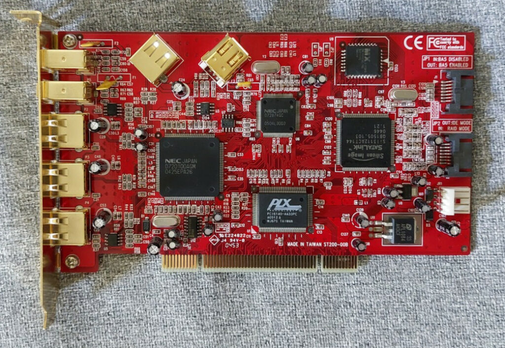
- A PCI Combo Card with SATA (150), USB 2.0 and FireWire 400.
- A 16GB SATA DOM (Disk on Module).
- A Sonnet 300MHz G3 upgrade with 1MB of 150MHz Level 2 Cache.
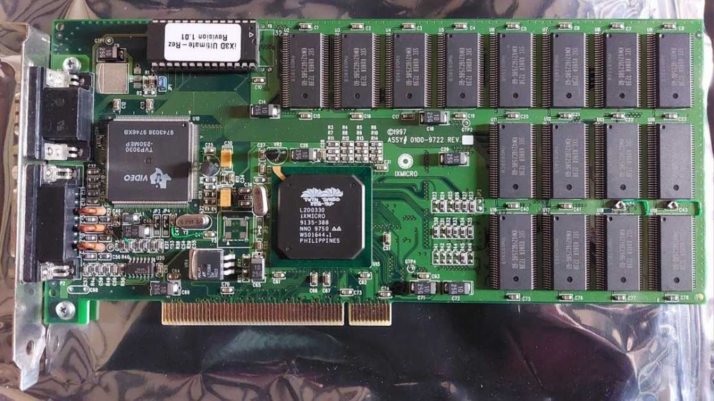
- An ixMicro ix3D UltimateRez – an 8MB video card with good 2D performance and some very basic QuickDraw3D acceleration.
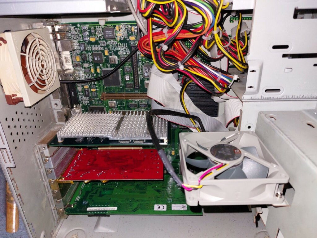
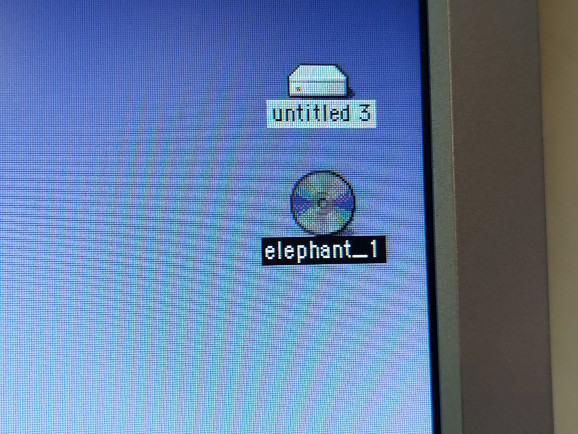
After installing the above, I also decided to install a Sonnet Tempo ATA133 card I recently got for a steal, not because I plan to use it long term in this machine, but because I found that the SCSI CD-ROM drive wasn’t working and the combination of the Sonnet Tempo and the IDE optical drive I had already installed to fill the open bay gives me a fast, bootable CD drive, that also reads DVDs and I think writes CDs. It will be a nice perk for now, until I work out what I want to do in the long term.
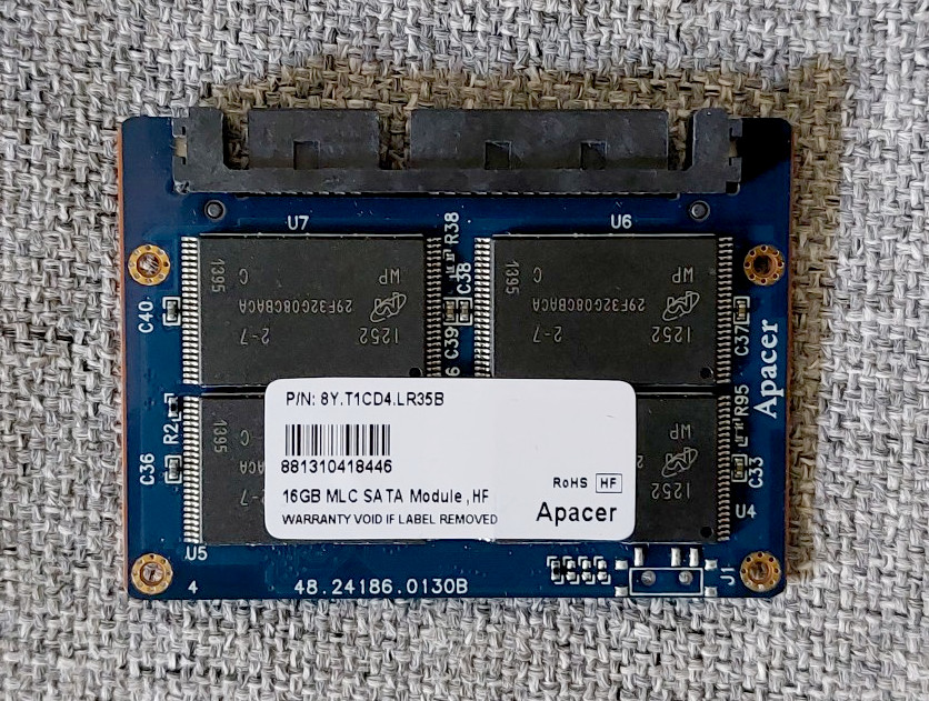
Installing a bootable, Mac compatible SATA card gives me the opportunity to use much cheaper but very fast drives, like this 16GB SATA DOM that I bought fairly cheaply from someone selling a number of them recovered from thin clients. While 16GB isn’t particularly large by modern standards, it is potentially eight times larger than the base 2GB configuration for the PowerTower Pro 225.
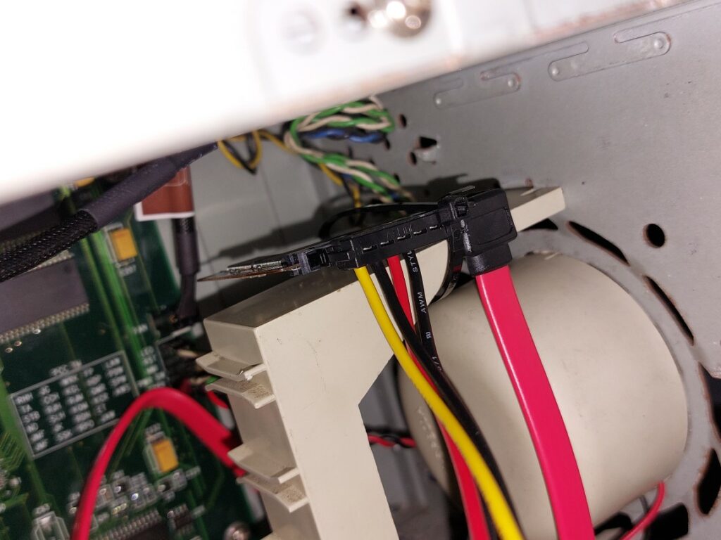
Because the DOM is an exposed circuit board, after looking around at the huge number of available drive bays (the PowerTower Pro seems to have a total of nine bays – four front 5.25″, two front 3.5″ plus the floppy drive and two internal 3.5″ bays in the cross brace / CPU bracket), I decided that the best place to mount it was with a cable tie on the long PCI card restraint bracket next to the speaker. Yes, it is probably the wrong thing to do, but it means that I don’t have to worry about electrical shorts!
The Sonnet processor upgrade solves the issue that I am missing the original Level 2 Cache. Since my had was sort of forced in this, I tried to aim for performance approximately where I thought the performance of the announced by never released PowerComputing PowerTower Pro G3, which allegedly had a 275MHz G3 with a 1:1 (275MHz) L2 backside cache. My G3 only has a 1:2 (150MHz) L2 backside cache, but it has a 300MHz CPU clock and a 50MHz host bus speed. Additionally, I believe I did see mention that PowerComputing intended to include a new, revised version of the ixMicro TwinTurbo video card, with improved performance and some 3D capabilities.
While the ix3D isn’t anything to write home about – it is a fairly fast 2D card with a high quality image output, capable of driving my 1280×1024 LCD at millions of colours it is likely a good pairing with the G3 and PowerTower. The early QuickDraw3D features are quirky, and not much use. If I remember, the card doesn’t support textured 3D, so you’re not going to be playing any fancy games on it, but it might be useful for some CAD modelling. Basically, I’m trying to resist the temptation to just slap a Radeon in the computer because doing so doesn’t keep it interesting with regards to what can and can’t I do on this machine. This card is much more period appropriate, while giving a little feature boost over the stock TwinTurbo cards. It does feel likely that this was a card that PowerComputing planned to ship with their G3 PowerTower Pro. The specific card I’ve installed has both an Apple RGB port and VGA, which is helpful when connecting monitors without adapters. I don’t believe the card is capable of running two monitors, that wasn’t a common feature at the time.
Interestingly, when I went to install PCI cards I found that their rear brackets aligned even worse than usual with the screw holes in the rear of the case. I solved this by loosening all eight logic board screws (you don’t need to remove the floppy drive bay FYI) and re-tightened them after pushing the board rearwards in the case.
So How Fast is My PowerTower Pro?
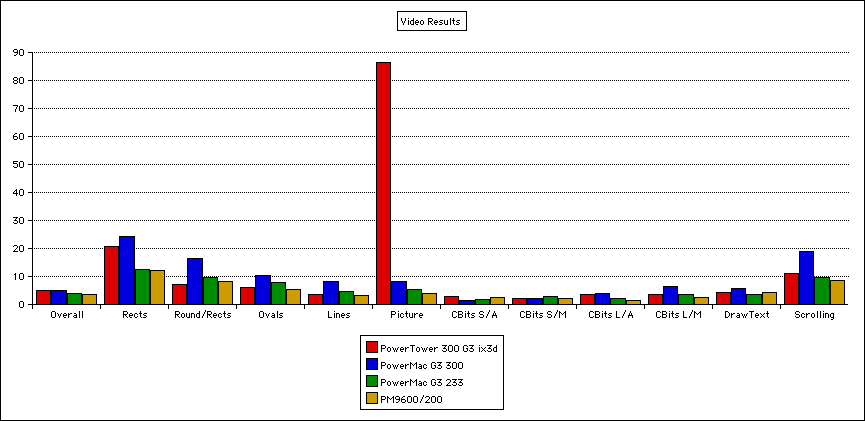
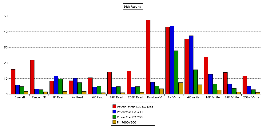
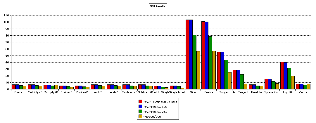
Now that we have something that resembles a computer, more than just a collection of parts, it feels like a good time to run some benchmarks. Keep in mind that at this point I only have a single 64MB RAM DIMM installed, meaning that I am not able to take advantage of memory interleaving (where the sequentially next memory address is pre-loaded ready, saving a little access time when you are accessing a block of contiguous memory). Additionally, ixMicro cards vary significantly in different aspects of performance depending on which driver version you have installed. I used the version labelled “2” during these tests, which if I remember, is a community version designed to add compatibility with later versions of classic Mac OS.
For comparison, I have also plotted results from a 300MHz Blue & White G3 (which would have 512k of 150MHz L2 Cache and a 100MHz system bus, compared to my 300MHz G3 with 1MB of 150MHz L2 Cache on a 50MHz system bus), a 233MHz Beige G3 (512k of 116MHz L2 and a 66MHz system bus) and a 200MHz 9600 (512k of 50MHz logic board cache (not backside like the G3s, or even “inline” like the later 250+ MHz 9600s). The Beige G3 has onboard ATI Rage II+ graphics, and the Blue & White has an ATI Rage 128 GL.
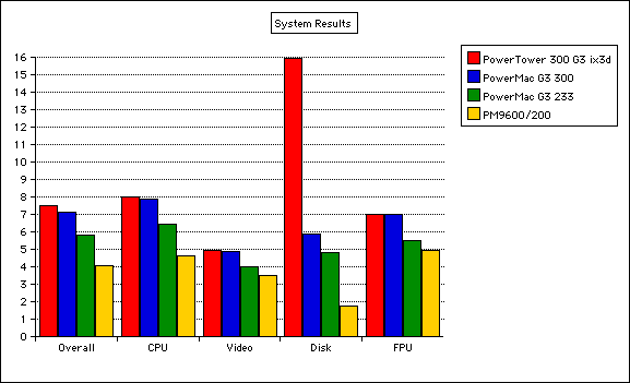
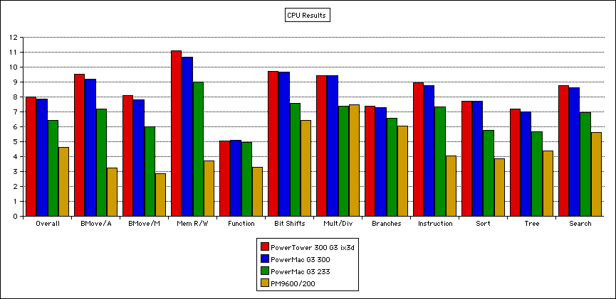
A large Cache always tends to disproportionately impact overall CPU performance. This is the reason for the small lead over the Blue & White. The Blue & White and the Beige will both have some advantage regarding RAM speed, which in the real world would be seen when working with large objects in RAM.
With the specific drivers I’m using for the ix3D, you can see an almost absurd level of performance for the “Picture” video test. This test draws an image to the screen, and then copies it lots of times randomly across the screen. This specific driver excels at this, possibly at the cost of performance for some of the graphics primitives compared to version 1 of the same. If I remember correctly, the Apple version of the driver has very good text rendering performance.
Disk performance of the SATA card and DOM are extremely good, especially compared to the 9600/200, and random read / write. The latter due to low seek times as there isn’t a mechanical mechanism needing to be physically moved.
FPU performance between the various G3s should basically just scale with MHz. Comparing the G3 and 604e in the 9600 is a little more tricky as they are fairly different and the 604e will perform better with code optimised for its particular characteristics. I don’t find a lot of meaning in the FPU chart.
Also, yes, for fun I did produce the plots in ClarisWorks 2.1. Please see some information about how I Benchmark my computers and how to extract Benchmark data for use in other software here. I converted the plots into a compatible format by using Cmd+Shift+4 to screenshot a region, and then used Photoshop 4.0 on the PowerTower to convert the screenshots into .PNG files.
Things I Have Done But Not Written Up Yet
- Ran some MacBench 4 benchmarks.
- Installed a Patched copy of iTunes 1.1. The visualiser only runs at 8fps unfortunately.
- Purchased some rust converter and zinc paint for where the plating has failed and some minor corrosion is showing.
- Installed 192MB of RAM.
- Installed a 500GB SATA 7200rpm Hard Disk.
Things I Should Look Into
- I need to investigate the SCSI CD-ROM Drive to see if I can get it working. Sometimes all they need is the lens cleaning, but often the laser diodes have also gone weak. Older ROM only drives often struggle to read home-written CDs to start with, so combined with the above it is often worth installing an IDE or SATA drive, or a USB PCI card and using an external USB writer if you can (obviously this isn’t possible for computers that don’t have PCI).
- I haven’t done anything much with the floppy drive yet. If nothing else, before I put any disks that I care about in it I need to take it to bits and clean the heads, although I’ve never been much of a fan of floppy drives, so “not using it” is a valid solution in my mind.
- I spent some considerable time searching eBay and was finally able to find some matched pairs of suitable (5v 168 pin FPM / EDO) memory. While 64MB is a reasonable amount, especially for Mac OS 7.6, I’d like to run 8.6 as the primary OS on this computer and ideally would like to run 9.1, including some RAM hungry software for image editing, video editing and music production.
- I need to fix whatever is wrong with the external sound port that means the computer always thinks a cable is plugged in. At the moment I just have a pair of Apple Design speakers plugged in.
- Who made the case and what other computers shipped in the same or similar cases, possibly as a source of spare parts.
- Are drive bay rails universal?