Tag Archives: example

ReadyAVR-64 – A board without documentation

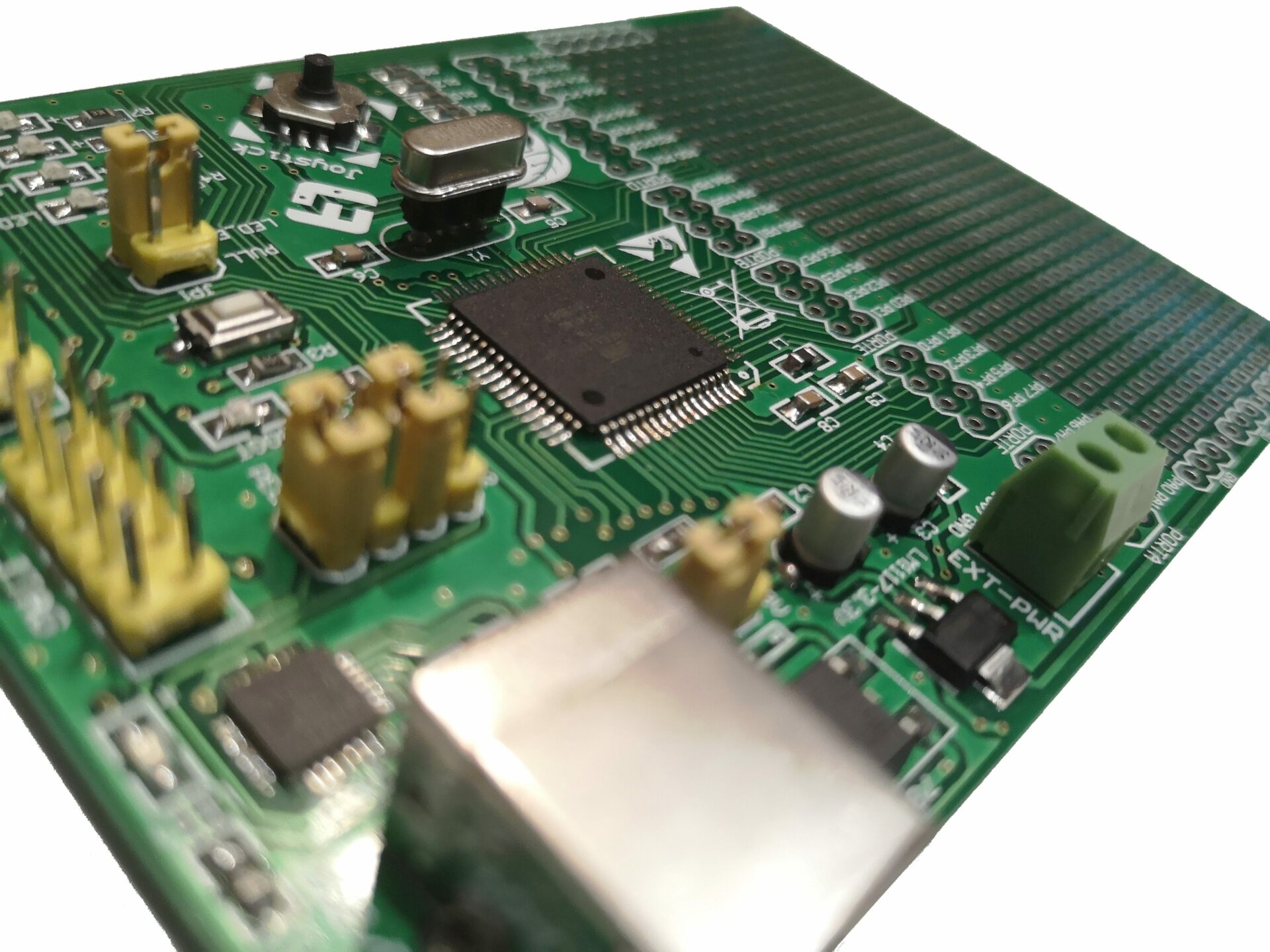
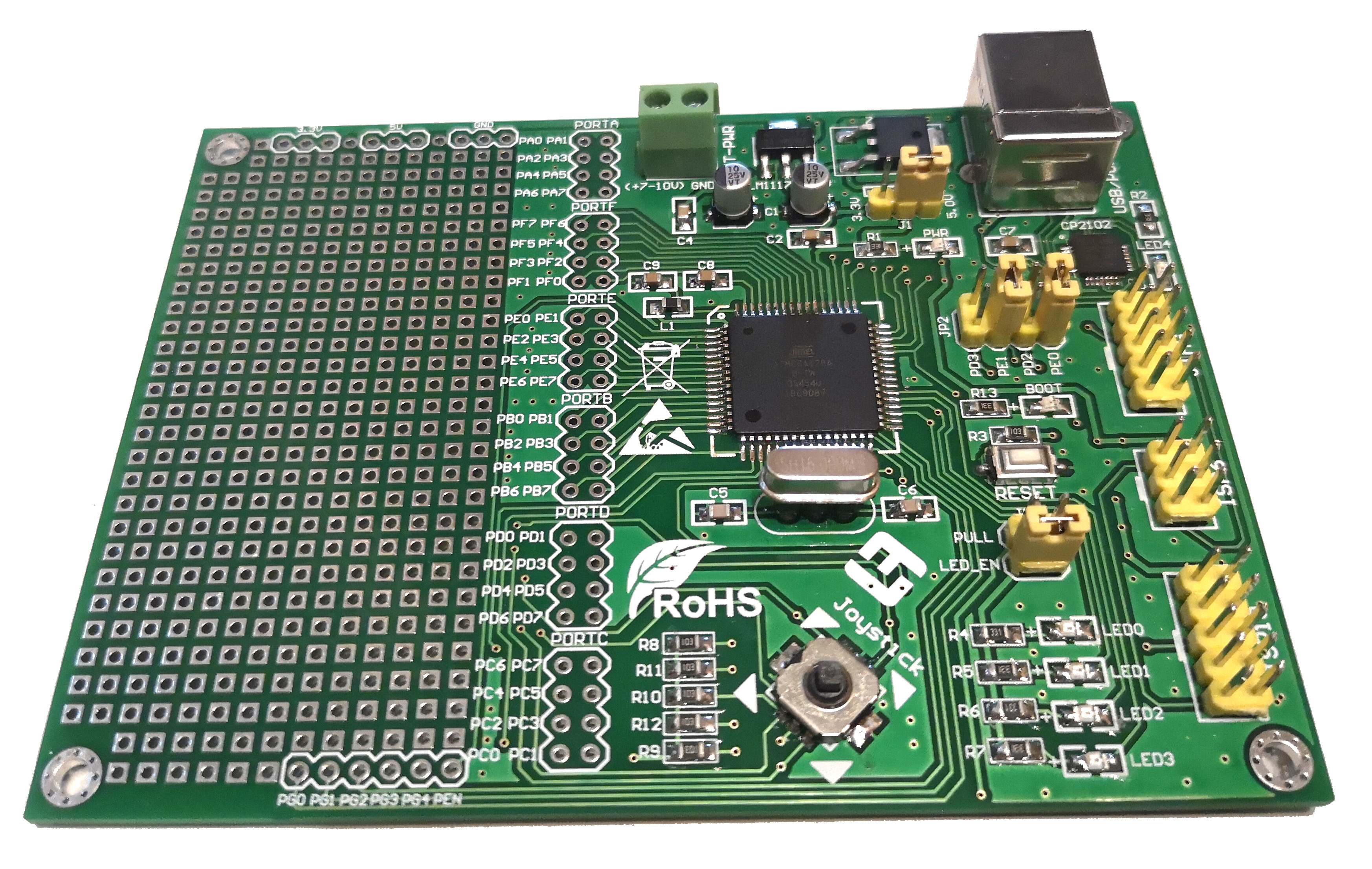
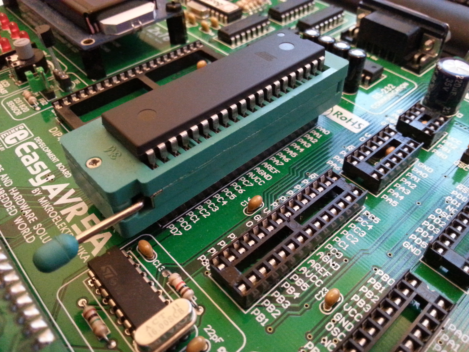
I recently purchased a Atmel ATmega128 breaout board designed by LogiFind, called the ReadyAVR-64. The company seems to be imitating Mikroelektronika with their naming conventions and produce intermediately priced educational boards. They provide some examples and software, oriented around Windows as a host platform for most of their boards. I have a couple of examples for there wares, from the giant “EasyAVR128” to the more basic “ReadyAVR-28” (which I plan to swap a ATmega328 into – they do a board with one pre-installed, but it costs more). Currently, the documentation download link on their website for their ReadyAVR-64 board seems to be broken.

Despite being a blue PCB in all adverts etc. the board I received in the post was green. I had some minor postage issues, with my package been returned to sender for an unknown reason, but the seller was very honest and quick responding and the item arrived by airmail a few days after I reported my concerns.
ReadyAVR-64
ReadyAVR-64

Upon getting my board in the post, the first thing I did was swap out the crystal oscillator for a turned pin socket. There are two reasons for this – firstly the pre-installed crystal was an odd speed (7.3728mhz – I prefer 16mhz), and secondly, a socket means I can change the speed as I wish. Making this change requires your usual component desoldering – I used some flux, an iron and some solderwick – once the crystal was out of the board I finished clearing the holes with a solder sucker. Break off a 3 long piece of turned pin female header and solder it in. You don’t even need to remove the middle pin as there is an unconnected hole already on the PCB.

The next thing I did was replace the pre-installed bootloader with a variant of optiboot. I can’t remember exactly where I got it, but the hex file is here. This USB bootloader uses the PE1, PE0 serial port and so I had to switch the jumpers on JP2 for it to work. Loading in the new bootloader is done through the ISP6 or ISP10 ports. I used my STK500 with AVRdude, as I’ve had some difficulties programming AVR128s with my usbasp in the past. It should be possible to follow “Arduino as ISP” instructions to reflash the board. I wont go into depth here. At some point I’ll write a guide to reflashing bootloaders onto AVRs, but there are already a lot of guides out there. For reference, I used the following two AVRdude commands to setup the bootloader and fuses on my board :

avrdude -p m128 -c STK500 -P /dev/ttyUSB0 -u -U flash:w:optiboot_atmega128.hex
avrdude -c STK500 -p m128 -P /dev/ttyUSB0 -U lfuse:w:0xff:m -U hfuse:w:0xc6:m -U efuse:w:0xff:m

At this point, if you wish to program the board using the Arduino IDE, you will need to install MegaCore. This adds extra microcontrollers, including the ATmega128 to the boards menu in the Arduino IDE. Installation is described in the “How to Install” section of the linked github page.

As I couldn’t find any documentation on the board due to the broken download link, I experimented and followed traces on the board until I worked out the following. Note that the LEDs are Active Low (setting the connected pin on the microcontroller to High turns them off).

  • LED0 = Arduino Pin 28 (PC0)
  • LED1 = Arduino Pin 29 (PC1)
  • LED2 = Arduino Pin 30 (PC2)
  • LED3 = Arduino Pin 31 (PC3)
  • BOOT = Arduino Pin 37 (PA7)

The Joystick is connected to Port B, but required the chip’s internal pullups to be enabled before it works correctly. One way this can be done in the Arduino IDE is by using digitalWrite to set the pin HIGH after having set it to be an input. Connections are as follows :

  • Joystick Up = Arduino Pin 9 (PB1)
  • Joystick Down = Arduino Pin 11 (PB3)
  • Joystick Left = Arduino Pin 10 (PB2)
  • Joystick Right = Arduino Pin 8 (PB0)
  • Joystick Click = Arduino Pin 12 (PB4)

Note that when you trigger two options at once, say for up and right, or left and click, all 5 pins trigger. The joystick connections are also Active Low, meaning the input goes low when the joystick is triggered.

The following Arduino example shows the functionality of both the LEDs and the joystick.

int LEDS[] = {28,29,30,31,37};
int Inputs[] = {8,9,10,11,12};

void setup() {
  for(int x = 0; x<5; x++){
    pinMode(LEDS[x], OUTPUT);
    digitalWrite(LEDS[x], HIGH);
  }
  for(int x = 0; x<5; x++){
    pinMode(Inputs[x], INPUT);
    digitalWrite(Inputs[x], HIGH); // enable pullup
  }

  int LED = 0;
  while(LED<5){
    pinMode(LEDS[LED%5], OUTPUT);
    digitalWrite(LEDS[LED%5], LOW);
    delay(250);
    digitalWrite(LEDS[LED%5], HIGH);
    delay(250);

    LED++;
  }
}

void loop() {
  for(int x = 0; x<5; x++){
    if(digitalRead(Inputs[x])==LOW){
      digitalWrite(LEDS[x], LOW);
    }else{
      digitalWrite(LEDS[x], HIGH);
    }
  }
}
USB Relay Boards

FTDI USB Relay Board

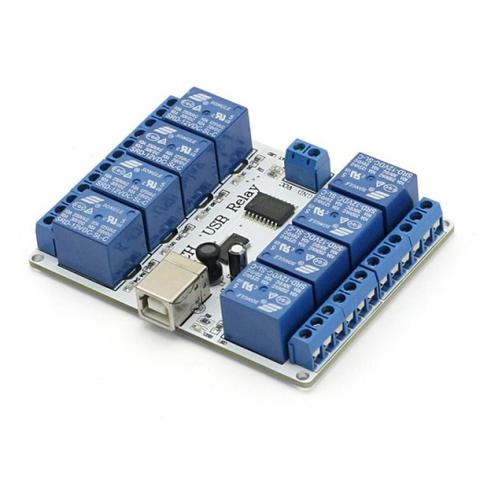
A while back I wrote a post about using an FTDI breakout board as a GPIO board from Python. Since then, I have discovered that there are USB relay boards based on this concept available from China. SainSmart seem to sell them, but they are available on ebay, Banggood and Aliexpress. The boards are interesting as they do not contain a microcontroller – just an FTDI chip and an ULN2803 array of Darlington pairs to drive the relay coils.

Relay Board
SainSmart 8 Channel USB Relay Board

Using the setup previously detailed in my other post, it is possible to control one of these boards from Linux. The process is exactly the same as using one of the little red USB UART adapter boards.

To use one of these boards from Linux :

  1. Follow the process to set up your computer as per my old post.
  2. Plug the board into a 12v DC supply, and your computer’s USB.
  3. Run the following example (as root / with sudo if you haven’t set up permissions for your user to access the device).
#!/usr/bin/env python

import os
import sys
import ftdi1 as ftdi
import time

ftdic = ftdi.new()
if ftdic ==0:
	print( 'new failed: %d', ret )
	os._exit( 1 )

# try to list ftdi devices 0x6010 or 0x6001
ret, devlist = ftdi.usb_find_all( ftdic, 0x0403, 0x6010 )
if ret <= 0:
    ret, devlist = ftdi.usb_find_all( ftdic, 0x0403, 0x6001)

if ret < 0:
    print( 'ftdi_usb_find_all failed: %d (%s)' % ( ret, ftdi.get_error_string( ftdic ) ) )
    os._exit( 1 )
print( 'Number of FTDI devices found: %d\n' % ret )
curnode = devlist
i = 0
while( curnode != None ):
    ret, manufacturer, description, serial = ftdi.usb_get_strings( ftdic, curnode.dev )
    if ret < 0:
        print( 'ftdi_usb_get_strings failed: %d (%s)' % ( ret, ftdi.get_error_string( ftdic ) ) )
        os._exit( 1 )
    print( 'Device #%d: manufacturer="%s" description="%s" serial="%s"\n' % ( i, manufacturer, description, serial ) )
    curnode = curnode.next
    i += 1

# open usb
ret = ftdi.usb_open( ftdic, 0x0403, 0x6001 )
if ret < 0:
    print( 'unable to open ftdi device: %d (%s)' % ( ret, ftdi.get_error_string( ftdic ) ) )
    os._exit( 1 )


# bitbang
ret = ftdi.set_bitmode( ftdic, 0xff, ftdi.BITMODE_BITBANG )
if ret < 0:
    print( 'Cannot enable bitbang' )
    os._exit( 1 )

for i in range( 8 ):
    val = 2**i
    #print( 'enabling bit #%d (0x%02x)' % (i, val) )
    ftdi.write_data( ftdic, chr(val), 1 )
    time.sleep ( 0.5 )

ftdi.write_data( ftdic, chr(0x00), 1)
time.sleep ( 0.2 )

ftdi.disable_bitbang( ftdic )
print( '' )


# close usb
ret = ftdi.usb_close( ftdic )
if ret < 0:
    print( 'unable to close ftdi device: %d (%s)' % ( ret, ftdi.get_error_string( ftdic ) ) )
    os._exit( 1 )

print ('device closed')
ftdi.free( ftdic )

This code is lightly modified from the code found here, without which I’d have struggled.

HID USB Relay Board

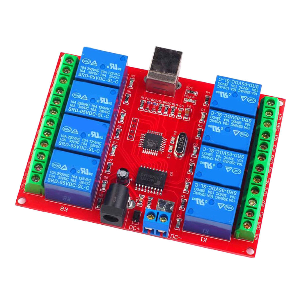
Similar boards exist which use an Atmel microcontroller interfacing with the computer through a software HID implementation. These boards are cheaper, but otherwise similar on the relay side and in appearance.

Red USB Relay Board
Red USB Relay Board

These boards can be controlled from Linux by installing the “usbrelay” program from the repository (on Ubuntu and Debian at least) using “sudo apt-get install usbrelay”. Otherwise the developer has a github page for the project here : https://github.com/darrylb123/usbrelay. Once installed and with the device connected, simply typing “sudo usbrelay” (without quote marks) at your command line reports back on connected devices. One of my devices calls itself “VXCMF”, while another calls itself “6QMBS”. Where a device is called “VXCMF”, the first two relays can be turned on with the following command “sudo usbrelay VXCMF_1=1 VXCMF_2=1” and off again with “sudo usbrelay VXCMF_1=0 VXCMF_2=0”.

If you want to use the boards without sudo, you’ll have to add it to /etc/udev/rules.d. There are detailed instructions on the github linked above, but in short, if you’re using a Debian family OS, put the following in a file called “50-usbrelay.rules” in the folder /etc/udev/rules.d :

SUBSYSTEM=="usb", ATTR{idVendor}=="16c0",ATTR{idProduct}=="05df", MODE="0666"
KERNEL=="hidraw*",  ATTRS{idVendor}=="16c0", ATTRS{idProduct}=="05df", MODE="0660", GROUP="plugdev", TAG+="systemd" ENV{SYSTEMD_WANTS}="usbrelayd.service"
KERNEL=="hidraw*",  ATTRS{idVendor}=="0519", ATTRS{idProduct}=="2018", MODE="0660", GROUP="plugdev", SYMLINK+="usbrelay%b"

SUBSYSTEM=="usb", ATTR{idVendor}=="5131",ATTR{idProduct}=="2007", MODE="0666"
KERNEL=="hidraw*",  ATTRS{idVendor}=="5131", ATTRS{idProduct}=="2007", MODE="0660", GROUP="plugdev", SYMLINK+="usbrelay%b"

Then make sure your user is in the plugdev group and restart. If you’re using Windows or macOS, there are other instructions in forks such as this one https://github.com/corerd/usbrelay, although it looks a little old.

Both boards detailed in this post are available with various numbers of relays. The red boards are probably easier to use as it is simply a case of installing usbrelay. Hopefully the instructions here and in my previous post can help people get their boards running. I haven’t tested, but both should work fine with a Raspberry Pi and many other SBCs.

Good luck!

GPIO Using a Cheap FTDI Board

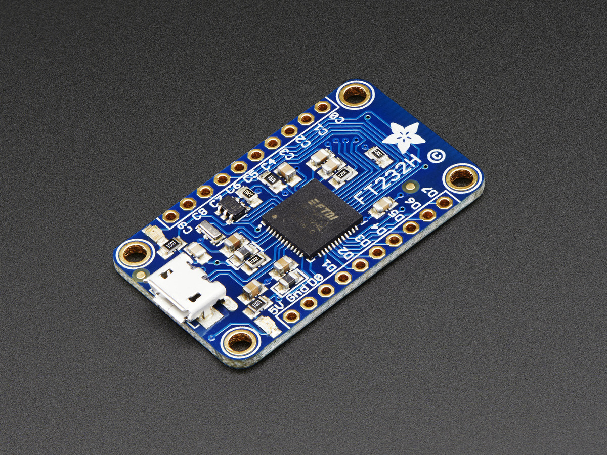
During a discussion with my dad about doing GPIO style projects from a regular, full fat computer,  I was telling him about the Adafruit FT232H Breakout board. These boards allow you to use several different serial protocols such as SPI, I2C and UART as well as provide a GPIO mode if you are willing to get involved enough. It provides an elegant solution to connecting external electronic devices, because it doesn’t require any software to be loaded into the device itself – all your code is running on your computer. The one downside is that, here in the UK at least, these boards cost in the region of £15, meaning that personally I would usually just grab a cheap Arduino and write some kind of pass-through program for most things I’d want to do.

AdafruitFT232H
Adafruit FT232H Breakout

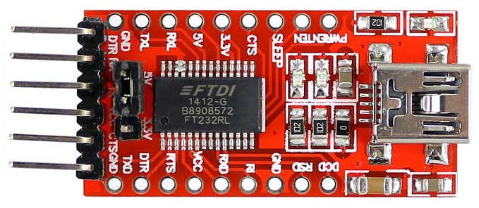
Yesterday evening, I installed the various software identified in Adafruit’s “Learning System” page relating to the product to allow me to set up various pins as inputs and outputs from a python program, in a similar style to how you might use the GPIO pins on a Raspberry Pi. Looking at what I needed to install and the fact that you had to specifically tell some of the libraries what chip you were connecting got me thinking that perhaps some of the software tools would work more generally with FTDI chips. I knew it was possible to use FTDI chips such as the FT232RL (commonly used in USB to UART serial adapters) as external USB connected GPIO, but my previous investigations hadn’t found clear (and simple enough) instructions to get anywhere in the time I had available. Today I dug out a cheap FT232RL based board and decided to have a play. At £1.38 each, these boards don’t exactly break the bank, and I have a pile of them already. I also like that you can easily switch the voltage using the jumper on these boards.

FT232RL
FT232RL USB to Serial Board

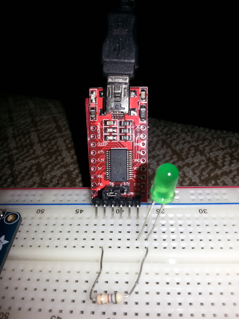
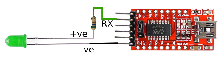
The following instructions relate specifically to Linux (Ubuntu 17.10), but following the instructions given on the Adafruit website may get you up and running on Windows or MacOS. Hardware-wise, any sensible computer with USB, a USB cable (Type A to Mini-B), a breadboard, a run-of-the-mill LED, an appropriate current limiting resistor (I used a 560 Ω resistor, which should be fine in most cases) and a FT232RL based board similar to the one above. The circuit is as follows (note the +ve side of the LED is identified by the longer lead, and the -ve by a flat on the side of the lens) :

FT232RL Circuit
FT232RL Circuit

Following the Adafruit instructions for Linux, carefully enter the following commands in a terminal :

sudo apt-get update
sudo apt-get install build-essential libusb-1.0-0-dev swig cmake python-dev libconfuse-dev libboost-all-dev
wget http://www.intra2net.com/en/developer/libftdi/download/libftdi1-1.2.tar.bz2
tar xvf libftdi1-1.2.tar.bz2
cd libftdi1-1.2
mkdir build
cd build
cmake -DCMAKE_INSTALL_PREFIX="/usr/" -DPYTHON_INCLUDE_DIR="/usr/include/python2.7" -DPYTHON_LIBRARIES="/usr/lib/python2.7/" ../
make
sudo make install

This installs the dependencies, fetches the source code for libftdi1, compiles it and finally installs it.

To test that everything installed correctly, launch the python interpreter by typing “python” (excluding quotes) at the command line and pressing enter, then type “import ftdi1” and press enter. If there are no errors, then it installed just fine. Exit the interpreter by typing “exit()” and pressing enter.

Now would probably be a good time to return to your home directory and perhaps create a folder for your python project. We’ll then create a new file called LEDBlink.py and open it in nano (a text editor) :

cd ~
mkdir ftdiGPIO
cd ./ftdiGPIO/
nano ./LEDBlink.py

Once you have the empty file open in the window, enter the following python program (which is based on the code found here). Note you can copy and paste from here – but use the copy button in the top right of the code container to ensure consistent formatting :

#!/usr/bin/env python

import ftdi1 as ftdi
import time

ftdic = ftdi.new()

# try to list ftdi devices 0x6010 or 0x6001
ret, devlist = ftdi.usb_find_all( ftdic, 0x0403, 0x6010 )
if ret <= 0:
    ret, devlist = ftdi.usb_find_all( ftdic, 0x0403, 0x6001)

# open usb
ret = ftdi.usb_open( ftdic, 0x0403, 0x6001 )

# bitbang
ret = ftdi.set_bitmode( ftdic, 0xff, ftdi.BITMODE_BITBANG )

for i in range( 64 ):
    ftdi.write_data( ftdic, chr(0x02), 1)
    time.sleep ( 0.5 )
    ftdi.write_data( ftdic, chr(0x00), 1)
    time.sleep ( 0.2 )

ftdi.disable_bitbang( ftdic )

# close usb
ret = ftdi.usb_close( ftdic )
print ('device closed')
ftdi.free( ftdic )

This is a basic program with no error checking – it assumes that a device of the correct type is connected an available. Note that it will probably need to be run as root to access the hardware. The program finds and connects to the FT232RL (assuming it is plugged in), then blinks the LED 64 times, being on for 0.5 seconds and off for 0.2 seconds each time. Once the code is entered, press ctrl-x, then “y” and finally enter to exit and save. Check that everything is wired up as follows :

FT232RL Circuit Breadboard

If everything is OK, plug the USB into the computer and enter the following commands :

chmod +x ./LEDBlink.py
sudo ./LEDBlink.py

The first command sets permissions to allow the python program to be executed, the second executes it. If all goes well you’ll be asked for your password and then the LED will start blinking.

If it doesn’t, then… erm… well it worked on my machine…

The following code does the same thing, but includes error checking. A lot of it!

#!/usr/bin/env python

import os
import sys
import ftdi1 as ftdi
import time

ftdic = ftdi.new()
if ftdic ==0:
	print( 'new failed: %d', ret )
	os._exit( 1 )

# try to list ftdi devices 0x6010 or 0x6001
ret, devlist = ftdi.usb_find_all( ftdic, 0x0403, 0x6010 )
if ret <= 0:
    ret, devlist = ftdi.usb_find_all( ftdic, 0x0403, 0x6001)

if ret < 0:
    print( 'ftdi_usb_find_all failed: %d (%s)' % ( ret, ftdi.get_error_string( ftdic ) ) )
    os._exit( 1 )
print( 'Number of FTDI devices found: %d\n' % ret )
curnode = devlist
i = 0
while( curnode != None ):
    ret, manufacturer, description, serial = ftdi.usb_get_strings( ftdic, curnode.dev )
    if ret < 0:
        print( 'ftdi_usb_get_strings failed: %d (%s)' % ( ret, ftdi.get_error_string( ftdic ) ) )
        os._exit( 1 )
    print( 'Device #%d: manufacturer="%s" description="%s" serial="%s"\n' % ( i, manufacturer, description, serial ) )
    curnode = curnode.next
    i += 1

# open usb
ret = ftdi.usb_open( ftdic, 0x0403, 0x6001 )
if ret < 0:
    print( 'unable to open ftdi device: %d (%s)' % ( ret, ftdi.get_error_string( ftdic ) ) )
    os._exit( 1 )


# bitbang
ret = ftdi.set_bitmode( ftdic, 0xff, ftdi.BITMODE_BITBANG )
if ret < 0:
    print( 'Cannot enable bitbang' )
    os._exit( 1 )

for i in range( 64 ):
    #val = 2**i
    #print( 'enabling bit #%d (0x%02x)' % (i, val) )
    #ftdi.write_data( ftdic, chr(val), 1 )
    #time.sleep ( 1 )
    ftdi.write_data( ftdic, chr(0x02), 1)
    time.sleep ( 0.5 )
    ftdi.write_data( ftdic, chr(0x00), 1)
    time.sleep ( 0.2 )

ftdi.disable_bitbang( ftdic )
print( '' )


# close usb
ret = ftdi.usb_close( ftdic )
if ret < 0:
    print( 'unable to close ftdi device: %d (%s)' % ( ret, ftdi.get_error_string( ftdic ) ) )
    os._exit( 1 )

print ('device closed')
ftdi.free( ftdic )

Line 51 turns on the LED connected to the RX pin on my board which is the second pin out of 8. Pins are defined as follows :

Pin #0 = 0x01
Pin #1 = 0x02
Pin #2 = 0x04
Pin #3 = 0x08
Pin #4 = 0x10
Pin #5 = 0x20
Pin #6 = 0x40
Pin #7 = 0x80

Obviously these are binary sequence in Hex, meaning each bit represents a pin. To turn on multiple pins at once, just add the values together. 0x00 on line 53 turns all pins off.

The example code I previously mentioned was the basis of this program also contains a commented out section showing how to use pins as inputs. It is commented out because it doesn’t work with Python 3, but should work fine under Python 2.x.

UPDATE…

I’ve discovered that SainSmart produce relay boards that work in a similar way to this. Building on the above, I have produced a new post showing how to use these with Python on Linux.