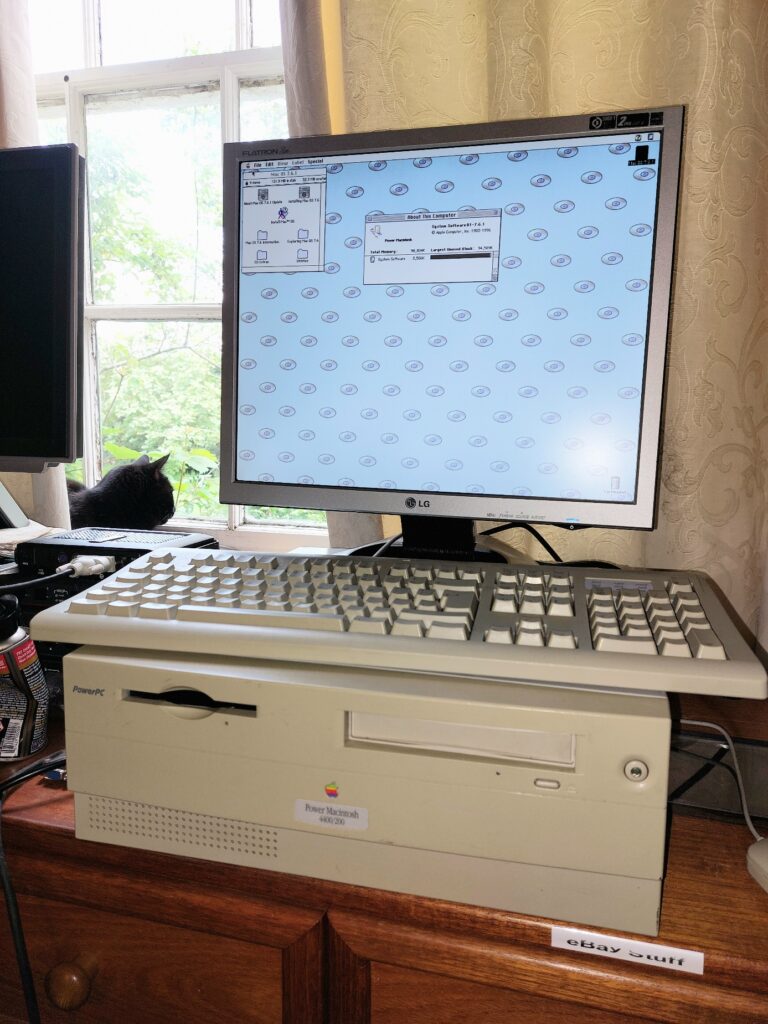
The Tanzania and Tanzania II logic boards were designed by Apple and mainly used by clone makers in machines such as Motorola’s StarMax series of computers. Apple released their own budget “clone” style computer in the form of the Power Macintosh 4400 (the 7220 in some markets).
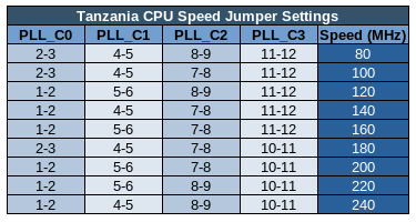
Tanzania based machines came in a verity of configurations with various speeds and a mixture of 603 and 604 family CPUs. What is interesting though is that Motorola variants have the PLL strapping settings detailed on the silkscreen! The PLL strapping is what sets the multiplier for the CPU clock speed.
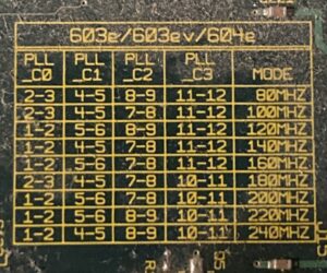
Note that the speeds shown in the “Mode” column are from a 40MHz bus machine. If you have a Tanzania II with a 50MHz bus, scale all of those speeds by multiplying them by 1.25 to get the equivalent speed for a 50MHz bus computer.
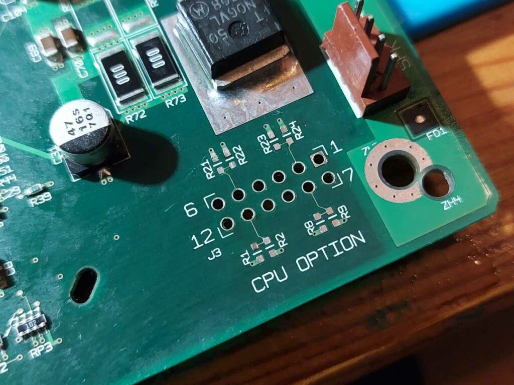
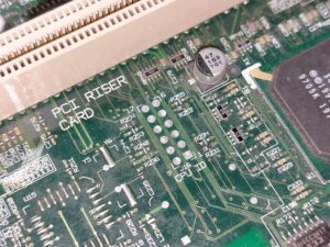
The numbers correspond to the pin numbers on the 12 pin header labelled “CPU Option” in the corner of the board closest to the CPU. By default the header is unpopulated and the clock speed is set by four pull up / pull down resistors on four of eight available positions around the header.
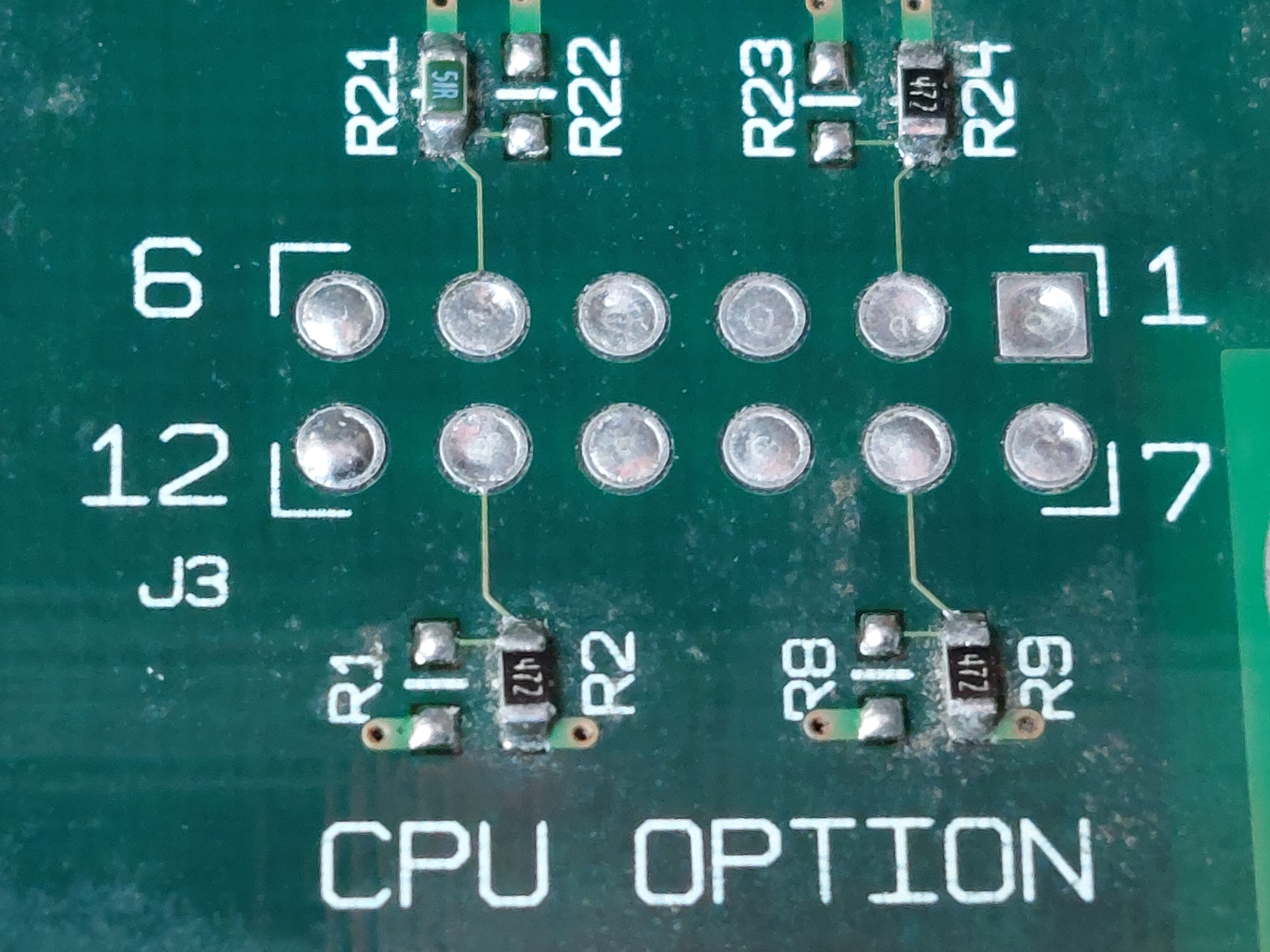
The pin numbering can be see around the footprint, and then populating R24 and not R23 is the equivalent of jumpering pins 1+2, while populating R23 and not R24 is equivalent to jumpering pins 2+3. This pattern repeats for pins 4 to 6 with resistors R21 & R22, 7 to 9 with R8 & R9, and lastly 10 to 12 with R1 & R2.
Each set of three pins can be thought of as a toggle switch, for example if you jumper 1+2 together you get one setting, and if you jumper 2+3 together, you get the other.
The resistors set the default and should be removed before jumpering or bridging the corresponding appropriate pairs in the 12 pin header (especially in the case of 51 ohm resistors). Never bridge all three pins in a set of three within the header or you will cause a short and possibly cause damage. Ideally, fit a pin header and use jumpers to change settings. You could even wire in a single pole double throw switch to each set of pins.
Target Speeds
Generally, I’ve found that most processors in various computers (but not all) overclock happily by 20% (I’m not specifically talking about Tanzania based computers, but vintage computers in general). Higher speeds might be achievable, but this is my personal rule of thumb for a ‘more likely than not’ stable overclock. This means that if you have a 160MHz machine, you can likely achieve the 180MHz setting. If you have a 200MHz machine, 240MHz is likely possible.
I haven’t worked out what the best way might be to do it, but given the CPU heatsink on the PM4400 is a little small, some additional cooling may be beneficial – either a larger heatsink similar to the one used on higher end Tanzania based clones, or a fan pointed at the CPU and powered from a spare molex (my PM4400 has several spare molex connectors, but you could always use a ‘Y’ splitter).
If your 160MHz can cope with 200MHz, a simple upgrade would be to remove resistor R1, and then bridge pins 10+11 on the CPU Option header, perhaps with a blob of solder. Removing the bridge and refitting the resistor would set it back to 160MHz.
Changing Resistors
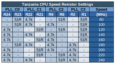
The following table shows what resistors to put where to set the speed of your Tanzania. You should never fit more than four resistors, but if you misplace one of the resistors, they look to be 0603 size, 4.7 kilo-ohm and 51 ohm resistors.
Fitting a Header
If you instead choose to fit a pin header and use jumpers to set the speed, you will first need to remove the resistors and then the existing solder from the footprint. To remove the resistors, I put a large blob of solder on the tip of my iron and used it to heat both sides of the resistor at once and brush them off the pads one at a time. To clear the solder filled through holes, I’d recommend using flux and solder wick (aka solder braid). I’d set my soldering iron to about 350°C, paint on some liquid flux, wick out some solder while not keeping the iron on a pin hole for more than about eight seconds at once, and always lift the iron and wick off at the same time to avoid the wick sticking and potentially causing damage.
If the solder doesn’t clear, try again from the other side. If it still doesn’t, add a little fresh solder and try again.
That is the tricky bit. Once cleared, solder in a 6×2 2.54mm pitch header, or two 6×1 headers.
The following representations show how jumpers should be fitted for a few common speeds.
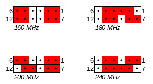
Note that the difference between 160MHz and 200MHz is only a single change, which is why, as mentioned previously, if you remove resistor R1 and then bridge pins 10 and 11 (for example with a blob of solder), your machine will be speed bumped to 200MHz from 160MHz, as long as it is able to run at 200MHz (the increase is 25%, which in general terms is quite a big speed increase for an overclock, especially without extra cooling).
Results
I removed the four resistors and cleared out the solder from the holes.
Then I soldered in a header, and fitted some green jumpers in the arrangement required for 240MHz. Reassembled my computer and powered it on.
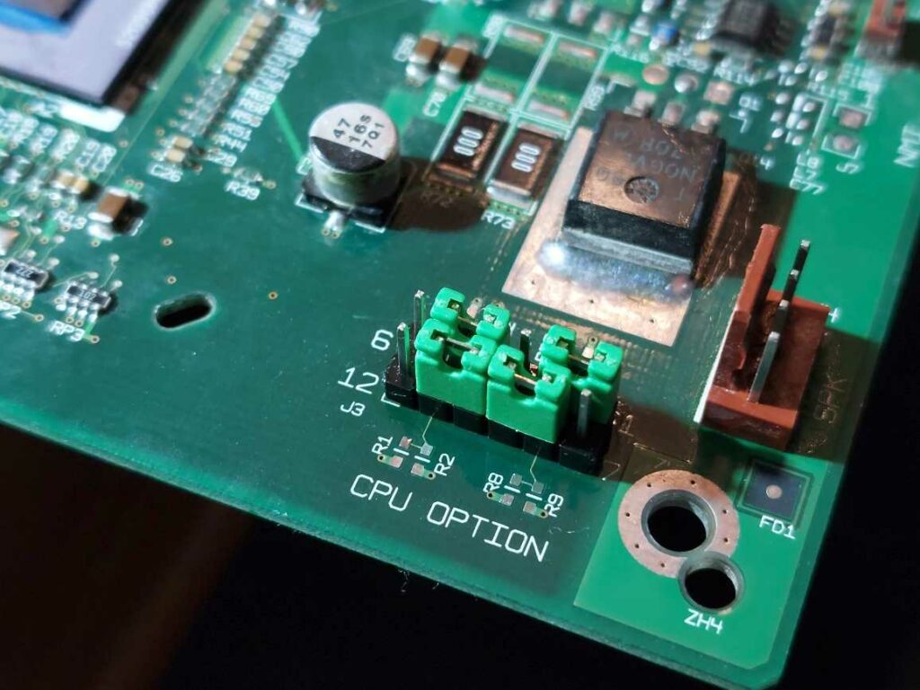
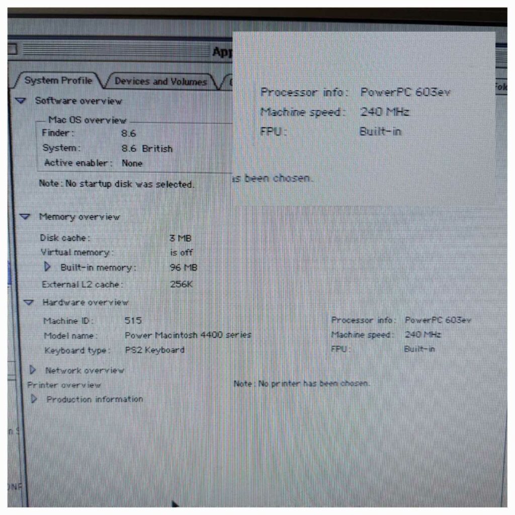
It booted happily and Apple System Profiler (in Mac OS 8.6) reports the CPU as a 240MHz 603ev, which is what was expected.
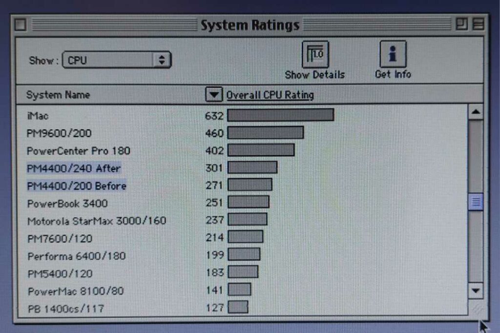
I ran some CPU benchmarks with the computer set to 240MHz and 200MHz (in that order, by powering down and swapping the jumpers around – I’d forgotten to get the “before” benchmarks) with Norton System Info from Norton Utilities 6 and got an 11% increase in the overall CPU score from the 20% overclock.
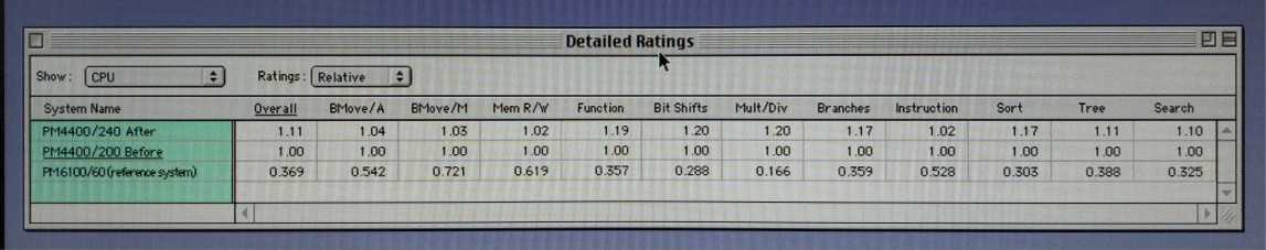
Looking at the detailed breakdown, we can see that tests that heavily use the RAM scored less well, with very RAM intensive tests seeing almost no change, moderately RAM intensive tests showing intermediate improvements and things like multiply and divide showing the full 20% uplift.
I checked through the other benchmark categories (Video, Disk and FPU), Video saw almost no change, likely because most actions are been undertaken by the built in ATI mach64 video chip, with the exception of Ovals and drawing images, which I assume are both dependant on the CPU. Disk saw no significant change (except for random write, which I don’t fully believe and so am going to assume was due to a hiccup during the 200MHz benchmark).
FPU scales almost exactly with clock speed as usual, so we basically see a 20% uplift across the board.
In my specific machine, the CPU heatsink is cool enough to comfortable touch (indefinitely) while overclocked to 240MHz, even with the stock heatsink. Interestingly at 200MHz the heatsink is actually cool to touch, it cant be much different in temperature to my hand. I feel like with a bigger heatsink this computer would have a lot of overclocking potential, although I’m already at the maximum speed in the table.
Upgrading to a 604e
The board is technically able to use either a 603e (/ 603ev) or a 604e BGA chip. To do this, you would have to at least adjust the CPU core voltage by changing components in the voltage regulation circuit near the speaker connector. You almost certainly would also have to change some other resistors on the board as this is usually the case. Unfortunately as I don’t have the schematics, I don’t know what or where these would be.
It may be possible to meticulously compare a 604 based board with a 603 board to document the differences, but I don’t envy the individual that does that. A good place to start is probably at the “CPU ID” header, which also seems to be surrounded by four strap resistors.
If I remember correctly, the Performa 6400 schematics are available, and this is a sort of similar machine in some ways, so probably contains some clues regarding changes needed to fit a 604 to a machine that shipped with a 603. The Beige G3 schematics might also help as the design includes allowances for the 603 and 604.
Bus Speed
I’ve not done any investigation, but glancing at the board, it looks like the chips “U10” and “U11” are clock sources. The “U10” style of clock is usually set to one of several speeds based on resistors on some of the pins, but given its location, it might be controlling something in the chipset as “U11” has a 40MHz clock and is closer to the CPU. U11 looks like a shift register – I’m not sure what the circuit is doing exactly. I’d have to look into it, but hopefully these comments are a helpful starting point for someone else.
An old 68kmla post with a dead link mentions a need to move a resistor from R29 to R28 (next to the VRAM slot). But I don’t know anything about that. Well, it actually says the reverse, but mine is already like that, so I’m assuming they got it backwards, or perhaps my machine is already set like that. Sadly the website they’re referencing didn’t get archived by the wayback machine.
Update – Good news, I seem to have found an archive of an alternative version of the page in question here : http://web.archive.org/web/20040120030611/http://home.t-online.de/home/andreas.kann/44002.htmlhttps://68kmla.org/bb/index.php?threads/tanzania-to-tanzania-ii-upgrade.34251/
Further information is that they had trouble with the rating of their L2 cache… The good news is I have a 50MHz cache from my 6500!
Looks like I just need to find myself a 50MHz crystal.