Making a Wombat Fast
Or, how to bump your Centris 650, Quadra 650 or Quadra 800 to 40 MHz with minimal effort.
Traditionally, the way we have overclocked the Wombat family of Macs (the 650s and the 800) is to desolder the CPU clock “G3” and replace it with a faster part, or alternatively, use a commercial product that “clips” onto the clock, disables it, and injects its own clock signal. Through a mixture of experimentation and, let’s be honest, the sudden availability of the schematics, I made the most awesome discovery, I’ve found that 40 MHz is easy without messing with the clock. This is great news, because…
- The clock is a surface mount part, meaning if you want to swap between speeds, you need to make a socket / adapter.
- The clock is right up hard against a NuBus slot meaning you have to be very careful when desoldering and soldering in the area.
It actually turns out that the logic board in these machines has a built in function that lets you select the clock source, either from G3, or a clock derived from the NuBus clock. Selecting the NuBus clock as a source just straight up runs your computer’s bus at 40MHz without having to do any particularly fiddly mods.
There are a number of “levels” of effort you can put in, each with different advantages and disadvantages. You can either just hard set your computer to 40MHz and overclock in terms of the timings (because the ROM still runs with 25 or 33MHz timings), change the timings to the correct ones for 40MHz by swapping resistors, or by adding an extra resistor and two jumper headings, make it that by just removing or fitting two jumpers, you can select (independently) the RAM/ROM/VRAM timings and the CPU clock speed (between either 20 and 25 MHz, or between 33 and 40 MHz).
Basic 40 MHz Overclock
This is the simplest overclock with the minimal effort.
Advantages – This is effectively an overclock, so you’ll get super fast video performance as well as fast RAM and ROM.
Disadvantages – This uses whatever timings you already have, so almost certainly be unstable if you have a machine that shipped as 25 MHz, and possibly unstable if you have a 33 MHz machine.
How to do the Basic 40 MHz Overclock…
- Remove the logic board from your computer and place it on a heat-proof and static safe surface suitable for soldering.
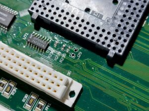
- Find the pair of pads next to the CPU called “J29” on the silkscreen.
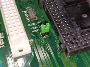
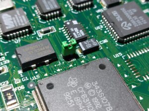
- Bridge the two pads, either with a blob of solder, or a little length of wire soldered between them. Alternatively, fit a two pin male header (2.54mm pitch) for a jumper.
- Reassemble your computer and test to see that everything works.
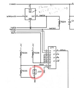
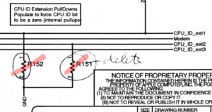
The modification works because U71 is wired to select between two clock sources depending on if J29 is fitted or not. As shipped, J29 is always open, ClkSel is always “high” and so the clock signal (half the bus speed) is always taken from G3. If you short J29, ClkSel goes low and the chip switches to using C20M – a 20MHz clock used by things like the SCSI and EtherNet chip, sourced from the NuBus circuit. Whichever clock is selected is doubled by the MC88916 chip before being fed into the CPU. Don’t worry that R235 isn’t fitted – it isn’t needed.
I recommend leaving a CPU in the socket while soldering to protect the socket from slips. In the photo above I’ve used solder wick / braid and flux to remove the solder that was in the through holes. You only need to do this if you want to fit a jumper (so you can select between the stock speed and 40 MHz by removing and fitting a jumper. The following shows my setup.
If you don’t already have a CPU heatsink, consider fitting one.
Adding 40 MHz Timings
This is a more stable solution that requires a little more soldering. This mod is required if your computer originally shipped as a 25 MHz machine.
Advantages – This reduces the overclock on systems such as RAM, ROM and VRAM, likely making the system more stable at 40 MHz. Doing this change will make a 25 MHz machine work at 40 MHz.
Disadvantages – Benchmarks will score a bit lower than using 33 MHz timings at 40 MHz (in line with a real 40MHz machine if Apple had ever released one). The machine ID (gestalt) will change to an unreleased Mac – 7.6.1 will boot OK (but might not install without tricking the installer), but 7.1 won’t boot unless you can find a hacked System Enabler. (Update – I believe I’ve managed to make the required changes and have the magic System Enabler working now. Drop me a message and I’ll send you a copy).
How to select 40MHz timings…
- Remove the logic board from the case and place it somewhere suitable to do some soldering.
- If there is a resistor fitted to R152, remove it.
- If there is a resistor fitted to R151, remove it.
- Save any resistors in case you want to put them back.
- Reassemble your computer and test to see that everything works.
The way I remove 0805 surface mount resistors is by putting a little flux on them, and then placing the iron on one end for about 3 seconds, before quickly moving the iron to the other pad and pushing the resistor off. Sometimes it takes a couple of tries, but it is easier than faffing with other methods and I usually already have my iron set up. It is especially helpful if there is plastic parts nearby on the board that hot air might damage.
The Ideal Setup
This last modification is closest (see the “Other Tweaks” section) to how I have my system configured as it gives the best flexibility. It lets you have jumpers to select CPU speed and timings. Removing both jumpers gives you the stock CPU speed (whatever it is on your machine), with (always) 33 MHz timings, while fitting both jumpers gives you 40 MHz and 40 MHz timings. You can also mix and match.
Advantages – Flexibility – you can change the CPU clock between stock (hopefully 33 MHz) and 40 MHz, and also the timings between 33 MHz and 40 MHz settings. All without even removing the logic board from the case (once the modification has been done).
Disadvantages – If you have a machine fitted with the original 12.5MHz clock for 25MHz, it will be slower than as shipped when you pick 25MHz by jumpers, because you will only be able to select timings designed for higher clocks.
If you have a 25MHz machine, I recommend just doing the first two mods above and basically hard wiring it to 40MHz. Make sure you have a heatsink fitted and consider finding a 33MHz grade CPU.
To fit dual jumpers…
- Remove the logic board to somewhere you can do soldering.
- Make sure no resistor is fitted at location R151.
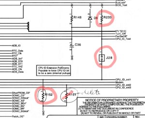
- Fit a 1.2k 0805 resistor (usually labelled 122) at location R152.
- Fit a 330 ohm 0805 resistor (usually labelled 331) at location R233.
- Fit a header at location J28.
- Fit a header at location J29 if you didn’t previously.
- Reassemble your computer and test to see that everything works.

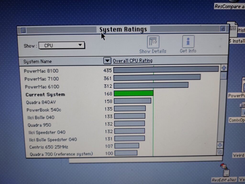
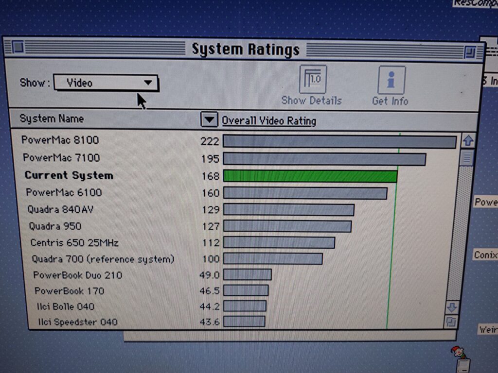
At this point, as described above and if you started with a 33MHz board, you will be able to select 33 MHz with 33 MHz timings by removing both jumpers (I store them by placing them so they are on only one pin of the header), or 40 MHz with 40 MHz timings by fitting both jumpers. If you fit J29 and not J28, you will get a 40 MHz bus / CPU speed, with 33 MHz timings. This is an overclock with regards to the timings, so you will have boosted video, RAM and ROM performance. Most noticeable in the video benchmarks like the following :
Note that while 40 MHz timings are selected, you will have the machine ID (gestalt) of an unreleased Mac, and System 7.1 won’t boot as mentioned above. If you want to boot in 7.1, just remove jumper J28.
Other Tweaks
- Fit a 40 MHz Grade CPU and a heatsink.
- Fit a socket for trying other clock speeds.
- Fit a 25MHz clock to aim for 50 MHz.
- Spoof a Quadra 800 power LED by shorting the appropriate two pins on the LED connector location. This makes your computer think it is a Quadra 800, which shipped with faster RAM, so I believe the ROM sets up slightly faster RAM timings.
- Install the Wish I Were control panel to override the machine ID gestalt and reduce (but not completely) the number of issues from running a machine with an unreleased ID.
- Replace the MC88916DW55 with an MC88916DW80 as this makes 50 MHz more likely in combination with a faster clock at G3. Fitting J29 still selects 40MHz, but removing it selects the faster clock at G3. Remember G3 is half the bus speed.
- Remove onboard RAM and fit a single stick of very fast RAM (50ns EDO).
- Fit a PowerPC Upgrade Card. Some will run at 80 MHz using the modifications described on this page.
I have personally done all the mods listed above to my machine, although I can’t promise they’ll all work for you, or are worthwhile.
Further Research
I worked out how to modify the System Enabler so that 40MHz works with System 7.1! Drop me a message if you want a copy. I might have previously posted it on Tinker Different – I forget.
Additionally, if your board shipped from factory with J28 and or J29 fitted, and especially R233 fitted, I’d be interested to hear from you. It’s likely that such a board would be a prototype and it would be great to check some component values.
This page is making a record of information I originally posted on 68kmla.